Resource Mapping
87
DLAP-3200-CF
Appendix B Resource Mapping
B.1 BIOS Mapping in SPI ROM
The chipset supports up to three SPI ROMs (SPI_CS0#,
SPI_CS1# and SPI_CS2#). The motherboard uses SPI flash
SPI_CS0# to select the SPI flash which stores ME firmware and
the system BIOS. The size of the SPI ROM is 16MB for H310, and
32MB for Q370 chipsets.
From a software standpoint, the serial peripheral interface (SPI)
resides in the memory mapped space. This function contains reg-
isters that allow for the setup and programming of devices that
reside on the SPI interface. The physical SPI ROM can be
accessed by putting an address into the flash address register.
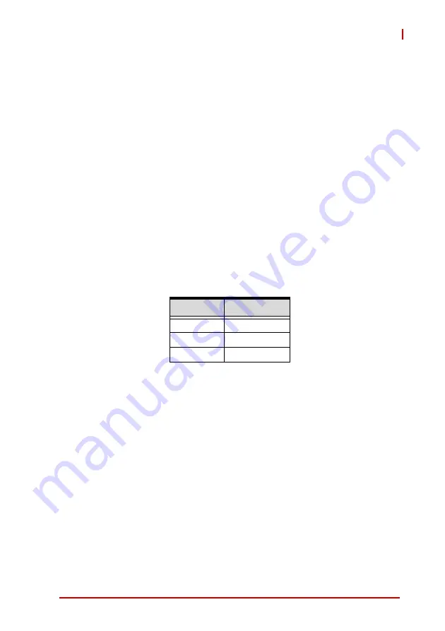
The motherboard SPI ROM mapping is as below.
Region
Size
Descriptor
4 KB
ME
8 MB - 4 KB
BIOS
8 MB
Содержание DLAP-3200-CF Series
Страница 2: ...ii Revision History Revision Release Date Description of Change s 1 0 2021 08 13 Initial release ...
Страница 8: ...viii List of Tables This page intentionally left blank ...
Страница 10: ...x List of Figures This page intentionally left blank ...
Страница 14: ...4 Introduction This page intentionally left blank ...
Страница 21: ...Specifications 11 DLAP 3200 CF Figure 2 3 DLAP 3200 CF Left Side View 194 50 182 00 ...
Страница 22: ...12 Specifications Figure 2 4 DLAP 3200 CF Right Side View 194 50 182 00 ...
Страница 23: ...Specifications 13 DLAP 3200 CF Figure 2 5 DLAP 3200 CF Rear View 235 00 ...
Страница 26: ...16 System Layout Figure 3 2 DLAP 3200 CF Rear Panel I O P N O ...
Страница 54: ...44 System Layout This page intentionally left blank ...
Страница 59: ...Getting Started 49 DLAP 3200 CF Left side screws ...
Страница 60: ...50 Getting Started Right side screws ...
Страница 62: ...52 Getting Started 3 Remove the 4 screws attaching the left drive bay to the chassis ...
Страница 68: ...58 Getting Started 8 After reinstalling the left and right side covers fasten all the screws at 6kgf cm torque ...
Страница 69: ...Getting Started 59 DLAP 3200 CF Right side screws ...
Страница 70: ...60 Getting Started Left side screws ...
Страница 71: ...Getting Started 61 DLAP 3200 CF Bottom screws ...
Страница 72: ...62 Getting Started 9 Install and lock the antennas as shown B key E key B key E key B key E key ...
Страница 84: ...74 Getting Started 2 Remove the 2 screws attaching the fan bracket to the chassis and disconnect the fan cable ...
Страница 85: ...Getting Started 75 DLAP 3200 CF 3 Remove the 8 screws attaching the BM cover to the chassis ...
Страница 86: ...76 Getting Started 4 Remove the BM cover ...
Страница 87: ...Getting Started 77 DLAP 3200 CF 5 Remove the fan ...
Страница 88: ...78 Getting Started 6 Remove the 2 screws connecting the PCIe bracket 7 Remove the PCIe bracket ...
Страница 94: ...84 Getting Started This page intentionally left blank ...
Страница 140: ...130 BIOS Setup This page intentionally left blank ...
Страница 150: ...140 Consignes de Sécurité Importante This page intentionally left blank ...


