Specifications
9
DLAP-3200-CF
2.3
Display Options
The DLAP-3200-CF includes six DisplayPort connectors, two Dis-
playPort signals from the CPU and four from MXM. All DisplayPo-
rts support DP++. Use DisplayPort1 (DP 1) to connect a monitor
when booting the system for the first time to properly access the
display settings in the BIOS menu. Refer to Appendix D, Display-
Port BIOS Settings for more information.
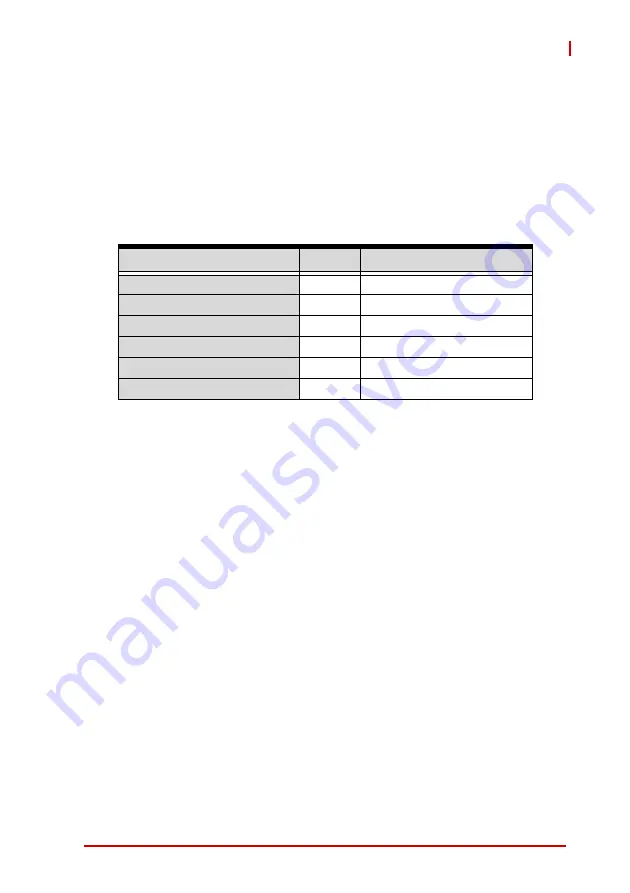
Table 2-1: Maximum Display Resolution
Port
Resolution
Display Port 1 from CPU
DP 1
4096x2304@60Hz
Display Port 2 from CPU
DP 2
4096x2304@60Hz
Display Port A from MXM
DP A
Based on MXM module
Display Port B from MXM
DP B
Based on MXM module
Display Port C from MXM
DP C
Based on MXM module
Display Port D from MXM
DP D
Based on MXM module
Содержание DLAP-3200-CF Series
Страница 2: ...ii Revision History Revision Release Date Description of Change s 1 0 2021 08 13 Initial release ...
Страница 8: ...viii List of Tables This page intentionally left blank ...
Страница 10: ...x List of Figures This page intentionally left blank ...
Страница 14: ...4 Introduction This page intentionally left blank ...
Страница 21: ...Specifications 11 DLAP 3200 CF Figure 2 3 DLAP 3200 CF Left Side View 194 50 182 00 ...
Страница 22: ...12 Specifications Figure 2 4 DLAP 3200 CF Right Side View 194 50 182 00 ...
Страница 23: ...Specifications 13 DLAP 3200 CF Figure 2 5 DLAP 3200 CF Rear View 235 00 ...
Страница 26: ...16 System Layout Figure 3 2 DLAP 3200 CF Rear Panel I O P N O ...
Страница 54: ...44 System Layout This page intentionally left blank ...
Страница 59: ...Getting Started 49 DLAP 3200 CF Left side screws ...
Страница 60: ...50 Getting Started Right side screws ...
Страница 62: ...52 Getting Started 3 Remove the 4 screws attaching the left drive bay to the chassis ...
Страница 68: ...58 Getting Started 8 After reinstalling the left and right side covers fasten all the screws at 6kgf cm torque ...
Страница 69: ...Getting Started 59 DLAP 3200 CF Right side screws ...
Страница 70: ...60 Getting Started Left side screws ...
Страница 71: ...Getting Started 61 DLAP 3200 CF Bottom screws ...
Страница 72: ...62 Getting Started 9 Install and lock the antennas as shown B key E key B key E key B key E key ...
Страница 84: ...74 Getting Started 2 Remove the 2 screws attaching the fan bracket to the chassis and disconnect the fan cable ...
Страница 85: ...Getting Started 75 DLAP 3200 CF 3 Remove the 8 screws attaching the BM cover to the chassis ...
Страница 86: ...76 Getting Started 4 Remove the BM cover ...
Страница 87: ...Getting Started 77 DLAP 3200 CF 5 Remove the fan ...
Страница 88: ...78 Getting Started 6 Remove the 2 screws connecting the PCIe bracket 7 Remove the PCIe bracket ...
Страница 94: ...84 Getting Started This page intentionally left blank ...
Страница 140: ...130 BIOS Setup This page intentionally left blank ...
Страница 150: ...140 Consignes de Sécurité Importante This page intentionally left blank ...


