Adept MobileRobots Pioneer LX Скачать руководство пользователя страница 79

Pioneer LX User's Guide, Rev. A

Page 79 of 125

Chapter 7: Connectivity

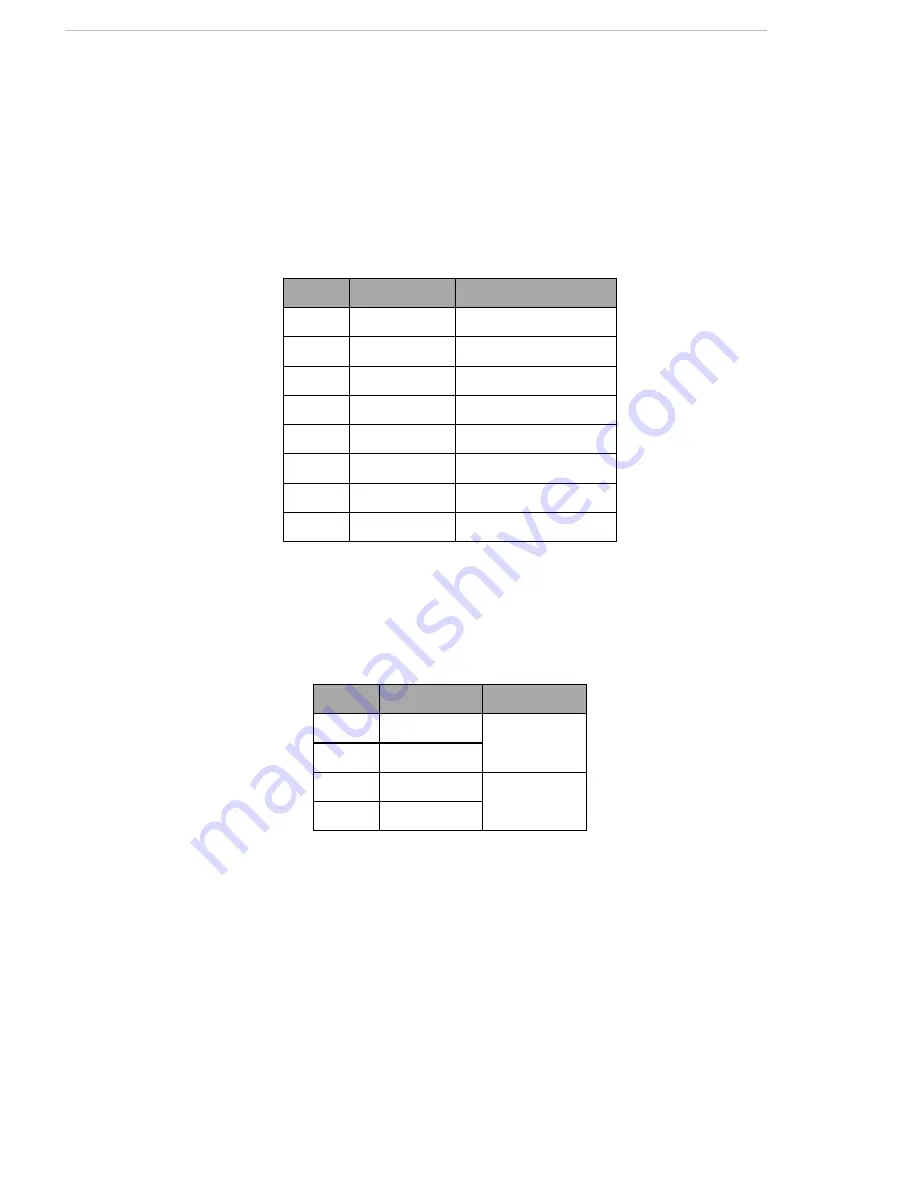
Pioneer LX Internal Power Pinouts

Bumper

Connection

Mini-Fit

®

4 x 2

Connector type

DB9F

Use

Front bumpers

Pin No.

Designation

Notes

1

BUMPER_R2L

Right, Channel 2, Low

2

BUMPER_R1L

Right, Channel 1, Low

3

BUMPER_L2L

Left, Channel 2, Low

4

BUMPER_L1L

Left, Channel 1, Low

5

BUMPER_R2H Right, Channel 2, High

6

BUMPER_R1H Right, Channel 1, High

7

BUMPER_L2H

Left, Channel 2, High

8

BUMPER_L1H

Left, Channel 1, High

Speakers

Connector type

Mini-Fit

®

2 x 2

Use

Speakers

Pin No. Designation

Notes

1

RIGHT+

Right Speaker

2

RIGHT-

3

LEFT+

Left Speaker

4

LEFT-

Содержание Pioneer LX

Страница 1: ...User s Guide Rev A November 2013...

Страница 2: ...ibility for any errors or omissions in the documentation Crit ical evaluation of the documentation by the user is welcomed Your comments assist us in preparation of future documentation Please submit...

Страница 3: ...tions 14 1 5 What to Do in an Emergency 14 1 6 Additional Safety and Standards Information 14 Adept Robot Safety Guide 14 1 7 Help Documentation and Support 15 Factory Repairs 15 Chapter 2 Setup 17 2...

Страница 4: ...tton 42 Brake release Button 43 Keyswitch 43 4 6 Other Controls and Indicators 43 Light Discs Light Tower 43 Joystick 44 MTX Lynx Core Diagnostic Indicators 45 4 7 Sensors 46 Laser Rangefinder 46 Sona...

Страница 5: ...ng 84 Tires 84 Axles 85 Lasers 85 Charging Station Contacts 85 8 3 Removing and Installing Covers 85 Cover Removal 86 Cover Installation 89 8 4 Replacing Periodic Parts 91 Battery 91 8 5 Replacing Non...

Страница 6: ...ion Initialization and Maintenance Commands 118 Robot Motor Velocity and Position Control 118 Configure Acceleration and Deceleration Parameters 119 Configure Maximum Speeds 119 Reset Position 119 Joy...

Страница 7: ...ctions to support your appli cation specific sensors and accessories Refer to Connectivity on page 61 for information on the available connectors For some projects you may want to customize the Pionee...

Страница 8: ...nal velocity clockwise counterclockwise The robot s controller will automatically control the robot s drive system to achieve those requested velocities using requested acceleration and deceleration p...

Страница 9: ...allation methods See Installing the Charging Station on page 24 A manual charging cord is included so you can charge the battery or a spare battery outside of the platform l Joystick Used for manually...

Страница 10: ...ler running MARCOS firmware handles the details of mobility including main taining the platform s drive speed and heading as well as acquiring data from the encoders and gyroscope and managing the pla...

Страница 11: ...sly navigate to goal points Refer to ARNL s README txt API reference manual and the guide Getting Started with ARNL Laser Navigation for more information ARNL updates and additional information are av...

Страница 12: ...tp robots mobilerobots com wiki Software All other accessory devices are supported in ARIA 1 2 Operating Environment The Pioneer LX is designed to operate in an environment that is wheelchair accessib...

Страница 13: ...s situation which if not avoided will result in death or serious injury WARNING This indicates a potentially hazardous electrical situation which if not avoided could result in serious injury or major...

Страница 14: ...of the platform with the charger attached Immediately disconnect the battery after opening the battery compartment door l Do not use parts not authorized by Adept l Do not use any charger not supplie...

Страница 15: ...list To contact MobileRobots customer support specialists regarding any questions not answered in this documentation or to troubleshoot problems with your robot visit http robots mobilerobots com wiki...

Страница 16: ......

Страница 17: ...mage the platform The crate with pallet for the platform measures 1219 x 711 x 762 mm 48 x 28 x 30 in and weighs 95 kg 210 lb Battery Storage NOTE If you purchased spare batteries this section applies...

Страница 18: ...in the same crate The joystick is in the smaller compartment on the near side in the previous figure The battery is shipped in a separate crate Additional optional accessories including cameras arms e...

Страница 19: ...ter 2 Setup Figure 2 2 Pioneer LX in Shipping Crate on Pallet with Crate Cover Lifting the Platform CAUTION You can damage the platform if you lift it incorrectly l Use two people to lift the platform...

Страница 20: ...there Lift the metal frame behind the plastic body panels not the plastic body panel Do not lift anywhere else Refer to the following figure Figure 2 3 Upper Side of Laser Slot at Sides NOT at Center...

Страница 21: ...etup Figure 2 4 Bottom of Inner Rear Cover Lift from the Frame not the Cover The following split photo shows a platform being lifted out of its crate 1 Lift the platform out of the crate 2 Re install...

Страница 22: ...ssembled but with battery packed separatey The battery is fully charged before shipping NOTE Air shipping regulations require that the platform be shipped without the battery installed Refer to Removi...

Страница 23: ...placed by one person using one hand in each of the grips as shown in the following figure Figure 2 7 Lifting the Battery The connectors for power and data go toward the rear of the platform 4 Attach t...

Страница 24: ...rom moving when the plat form docks Both the wall bracket and floor plate are included with each charging station CAUTION It is very important that the charging station be mounted with one of these me...

Страница 25: ...ount and Floor Mount Units are mm in Wall Mount Bracket 98 20 3 8 0 8 3x 6 0 25 8x 25 1 0 18x 6 0 25 Figure 2 8 Charging Station Wall Mount 2 Screw the two shoulder bolts each with a washer into the r...

Страница 26: ...for this Floor mount with Floor Plate This mounting method uses the floor plate The floor plate is not shipped attached to the charg ing station so you must attach it for this type of mount It will be...

Страница 27: ...ched to the floor as the weight of the robot on the floor plate will keep the charging station from moving Figure 2 10 Underside of Charging Station Foot Showing Screw Locations NOTE These are the thr...

Страница 28: ...r LX User s Guide Rev A Page 28 of 125 Chapter 2 Setup Figure 2 11 Charging Station Mounted on Floor Plate 406 16 0 495 19 5 Free Standing Units are mm in Figure 2 12 Charging Station Floor Plate Dime...

Страница 29: ...ee the following figure The height of the contacts should be set so that the roller is high enough to stay in contact with the platform as it is docking but low enough so that the bi level of the roll...

Страница 30: ...have been configured with the following default settings Wireless Network Interface wlan0 ESSID Wireless Network Static Address Address 10 0 126 32 Netmask 255 255 255 0 External Ethernet Connection M...

Страница 31: ...ork See http robots mobilerobots com wiki Linux_Network_Configuration for more information on configuring Linux network settings Configuring Windows Network Settings To change network settings in Wind...

Страница 32: ......

Страница 33: ...iki Software Run MobileSim and select the pioneer lx robot type 2 If using the actual robot log in to the onboard computer using ssh or log in at the con sole and start a terminal session Log in as gu...

Страница 34: ...the example server to integrate ARNL into your own software To use MobileEyes on your laptop or other computer download and install MobileEyes from the CD or from http robots mobilerobots com wiki Mob...

Страница 35: ...to the ARNL introduction for mapping instructions http robots mobilerobots com docs all_ docs ARNL introduction pdf Quick reference instructions on creating maps for ARNL is available in the ARNL doc...

Страница 36: ......

Страница 37: ...x2 Drive Wheel x2 Front Caster x2 Rear Caster x2 Rear Sonar x4 Joystick Ethernet Access Panel Battery Access Door Payload Bay Core Mounting Bracket 4 1 Operating Environment The Pioneer LX is designe...

Страница 38: ...with ARNL Laser Navigation for information on running the ARNL laser navigation servers and using them for autonomous operation of the robot 4 3 Startup and Shutdown Press and hold the power ON butto...

Страница 39: ...oximately 3 5 hours Battery Indicators and Controls The battery module has one push button and four LEDs From left to right they indicate LED Color Meaning 1 Red Error condition Green 25 state of char...

Страница 40: ...up to a 10 second delay between when a robot docks and when the charg ing LED turns on If the robot is fully charged the Charging LED will also turn off Powering ON or OFF the robot or connecting and...

Страница 41: ...tact Adjustment on page 29 Manually Charging the Battery Inside the Platform To manually place the platform on the dock for recharging first engange the E STOP button While holding the Brake Release b...

Страница 42: ...er after an E Stop has been pressed OFF Button The red OFF button removes power from all systems except the charging hardware circuits The platform s software systems prevent loss of data on shutdown...

Страница 43: ...by software to indicate status or state A user supplied light tower can also be added for extra signaling Several modes are available with different colors and patterns displayed on the light discs an...

Страница 44: ...2 orange alternate OUT4 buzzer periodic with OUT1 8 Motion Turn Signal Blue arcs rotate orange segment flashes on right or left side OUT1 green periodic OUT4 buzzer periodic 9 Motion Blue arcs rotate...

Страница 45: ...esired NOTE The Joystick handle should be facing you not away from you The joystick s GOAL button secondary button is for marking positions while making a map scan for ARNL WARNING The Pioneer LX may...

Страница 46: ...itioned at about 191 mm 7 5 in above the floor In most environments the sensor will provide highly accurate data Glass mirrors and other highly reflective objects cannot be reliably detected by the la...

Страница 47: ...r on the rear upper core in the payload bay Internal Sensors Encoders and Gyroscope Each wheel has an encoder that tells the robot controller how far the wheel has turned and in which direction Each w...

Страница 48: ......

Страница 49: ...via a simple packet based protocol See Communication Packet Protocol on page 113 via a serial connection between the robot and the embedded computer To support development of software MobileRobots pr...

Страница 50: ...ion parameters previously set until the platform either achieves the requested speed for velocity commands or nears the requested movement distance when per forming MOVE HEAD and DHEAD commands Rotati...

Страница 51: ...ng and sophisticated localization algorithms to correct the position of the robot with respect to features within a known and mapped environment You may translate and rotate the robot into a new coord...

Страница 52: ...ion about programming with the ARNL laser navigation and localization libraries read BaseArnl README txt ARNL README txt file LICENSE txt file and the BaseArnl API Reference Documentation and Arnl API...

Страница 53: ...ht the center of gravity of the entire robot needs to be considered This is particularly important if you intend to equip the Pioneer LX with a robot arm which would be lifting items off center from t...

Страница 54: ...run at an average of 50 full speed you would use the value of 94 from the table If your payload includes a device that draws 150 watts half of the time add 75 150 50 to 94 to get 169 Watts total Divid...

Страница 55: ...2 431 17 0 Figure 6 1 Platform Frame Dimensions for Attaching Payload Center of Gravity As much as possible you should keep the payload center of gravity centered on the Pioneer LX and as low close to...

Страница 56: ...ts listed The center of gravity in each instance needs to be within the area shown All units are mm NOTE These figures show the limits of where the payload center of gravity can be placed You should t...

Страница 57: ...Pioneer LX User s Guide Rev A Page 57 of 125 Chapter 6 Payloads 30 kg Figure 6 4 Center of Gravity Graphs 30 kg 60 kg...

Страница 58: ...mounting holes pretapped for 5mm metric screws M5 screws as well as one 1 4 hole in the center as well as locations to attach a camera mounting plate via three M3 screws The mounting deck is attached...

Страница 59: ...ayload with just one cable The cutout needed for mounting the Operator interface is shown in the following figure 0 7 06 0 28 23 02 0 91 42 07 1 66 61 12 2 41 77 06 3 03 84 14 3 31 89 51 3 52 5 39 0 2...

Страница 60: ......

Страница 61: ...d for the embedded computer on the top plate at the rear of the robot These are internally con nected to the computer USB ports on the MTX Core VGA Monitor Top plate A VGA display connector for the em...

Страница 62: ...ept components Digital I O HDB44F HDB44F 16 digital inputs in 4 banks of 4 Each bank can be wired as active high or active low depending on the connection of the BANK ter minal V IN range for each inp...

Страница 63: ...30 V Range R in 3 9 k 5 BANK1 Common for INPUT_1 X 6 INPUT_2 1 Input_2 1 0 30 V Range R in 3 9 k 7 INPUT_2 2 Input_2 2 0 30 V Range R in 3 9 k 8 INPUT_2 3 Input_2 3 0 30 V Range R in 3 9 k 9 INUIT2 4...

Страница 64: ...PUT_6 Output_6 27 OUTPUT_7 Output_7 28 OUTPUT_8 Output_8 29 OUTPUT_9 Output_9 30 OUTPUT_10 Output_10 31 OUTPUT_11 Output_11 32 OUTPUT_12 Output_12 33 OUTPUT_13 Output_13 34 OUTPUT_14 Output_14 35 OUTP...

Страница 65: ...state voltage range 0 to 1 3 VDC ON state voltage range 4 to 30 VDC Operational current range 0 to 7 5 mA OFF state current range 0 to 0 5 mA ON state current range 1 0 to 7 5 mA Impedance V in I in 3...

Страница 66: ...current range per channel I out 500 mA ON state resistance I out 0 5 A R on 0 14 85 C Output leakage current I out 5 A DC short circuit current limit 0 7 A I LIM 1 7 A Figure 7 3 Typical Digital Outp...

Страница 67: ...30 V Range R in 110 k 6 ANALOG_IN6 0 30 V Range R in 110 k 7 ANALOG_IN7 0 30 V Range R in 110 k 8 ANALOG_IN8 0 30 V Range R in 110 k 9 ANALOG_OUT1 0 20 V Range 10 mA Ro 200 10 ANALOG_OUT2 0 20 V Range...

Страница 68: ...ral purpose 1 2 Connector type DB9M Use Port 1 and 2 General Use The user serial ports use dev ttyUSB9 and dev ttyUSB10 device interfaces on Linux Pin No Designation Notes 1 4 6 9 No Connection 2 RS23...

Страница 69: ...s Operator Panel ON Additional user supplied OFF button same function as Operator Panel OFF Additional user supplied E Stop User Bumpers Mini Fit2 x 4 Payload bumpers user supplied con nected between...

Страница 70: ...4 A Switched 22 30 VDC 1 battery 10 A Switched 22 30 VDC 1 battery 10 A Safe Switched 10 A Switched and 10 A Safe Switched share the 10 A of current Each supply has an associated LED which when lit in...

Страница 71: ...N Short to FBAT_ALWAYS to signal OFF min 1 s pulse 9 START_BUTTON Short to FBAT_ALWAYS to signal ON min 1 s pulse 10 MOTOR_BRAKE Short to FBAT_ALWAYS for manual brake release 11 ESTOP_USR_1H Short 4 1...

Страница 72: ...Pioneer LX User s Guide Rev A Page 72 of 125 Chapter 7 Connectivity Figure 7 5 E Stop Jumper on Lynx Core Figure 7 6 E Stop Chain Diagram...

Страница 73: ...mper hit 3 USER_BUMPER_3 Short to ESTOP_SRC to signal bumper hit 4 USER_BUMPER_4 Short to ESTOP_SRC to signal bumper hit 5 USER_BUMPER_5 Short to ESTOP_SRC to signal bumper hit 6 USER_BUMPER_6 Short t...

Страница 74: ...Out_2 VBAT 5 A max switched in SW 9 10 SW_VBAT_OUT34 Battery_Out_3_and_4 VBAT 10 A max switched in SW Limit to 5 A per pin 11 12 SAFE_VBAT_OUT SW_VBAT_OUT34 gated by dual channel ESTOP relays Joystick...

Страница 75: ...3 MOTOR_BRAKE 4 5 ESTOP_FP_1H _2H 6 RS422_HMI_RX 7 RS422_HMI_RX 8 START_BUTTON 9 10 ESTOP_FP_1L _2L 11 HMI_5V_SW HMI_Power 12 14 GND 13 OFF_BUTTON 15 FBAT_ALWAYS Core Side Digital Ant1 Ant2 Audio In A...

Страница 76: ...mpers Sonar 2 DB9M Reserved for future accessories Aux Sensors Reserved for future accessories Charge Contacts Mini Fit Sr 2 pin For docking station Located underneath robot at rear Debug DB9M Reserve...

Страница 77: ...status indicator light discs on the platform sides Designation Pin No Hardware Software Notes 1 2 CANL_A CAN Communication differential pair 3 4 GND Direct GND 5 SHIELD GND Bead filter to GND 6 7 CANH...

Страница 78: ...ttyUSB4 See Programming on page 49for more information on connecting with soft ware Designation Pin No Hardware Software Notes 1 RS422_LIDAR_RX Connections to Adept Supplied LIDAR 2 RS422_LIDAR_RX 3 O...

Страница 79: ...1 BUMPER_R2L Right Channel 2 Low 2 BUMPER_R1L Right Channel 1 Low 3 BUMPER_L2L Left Channel 2 Low 4 BUMPER_L1L Left Channel 1 Low 5 BUMPER_R2H Right Channel 2 High 6 BUMPER_R1H Right Channel 1 High 7...

Страница 80: ...onnections to the Adept Supplied Battery 2 RS232_BATT_RXD 3 RS232_BATT_TXD 4 FBAT_ALWAYS 5 START_BUTTON 6 OFF_BUTTON Sonar 1 2 Connector type DB9M Use Platform sonar sensors The sonar communications i...

Страница 81: ...signation Notes 1 AUXS_A_TXD 2 AUXS_B_TXD 3 AUXS_C_TXD 4 5V_SW1 5 V 1 A shared with USB port 1 5 10 SW_20V_A 20 V 300 mA 6 7 8 GND 9 5V_SW2 5 V 1 A shared with USB port 2 11 AUXS_A_RXD 12 AUXS_B_RXD 1...

Страница 82: ......

Страница 83: ...e parts replacement for the Pio neer LX and the charging station Lynx Core Platform Sonar Controller Safety Scanning Laser Bumper Front Sonar x4 Light Disc x2 Drive Wheel x2 Front Caster x2 Rear Caste...

Страница 84: ...ive motors and gearbox are sealed and permanently lubricated so they do not require periodic maintenance Cleaning The following table gives a summary of cleaning procedures for the Pioneer LX Table 8...

Страница 85: ...fore starting Remove the power cord at the charger Clean the contacts with isopropyl alcohol CAUTION Do not lubricate the charging station paddle Lubrication will reduce the life of the paddle 8 3 Rem...

Страница 86: ...one of the light disc controllers Rear Inner Cover Battery This provides access to the battery compartment door 1 Pull the bottom of the cover away from the platform chassis This is easiest if you gri...

Страница 87: ...ry the cover away from the chassis Bumper Cover This is the only cover that requires tools to remove 1 Remove the screws at the sides of the cover Retain the screws for installing the new bumper cover...

Страница 88: ...with Connectors Still in Chassis 3 Unscrew all four sonar connectors Ensure that both sides of all connectors are labeled and match If not label them Figure 8 3 Sonar Connectors with Connectors Expose...

Страница 89: ...on Rear Outer Cover This cover houses the four rear sonar units which must be reconnected once the metal brace across the bottom is in the clip just below the battery access hole 1 Slide the metal bra...

Страница 90: ...ch side of the gap stick out the same amount away from the chassis This is most likely to be uneven near the top of the cover 5 If either edge sticks out more than the neighboring cover pull the neigh...

Страница 91: ...cing Periodic Parts Battery The battery is expected to last for approximately 7 years of 16 hours day 5 days week Life expectancy for 19 7 is 4 years 19 hours day is full time with time out to recharg...

Страница 92: ...y See the following figure Figure 8 5 Battery Cable Connectors 3 Slide the battery back and out of the platform There is a hand grip at the front and the rear of the battery to help you lift it Instal...

Страница 93: ...e 8 6 Battery Compartment Door keys are zip tied for shipping 3 Lift and slide the new battery into the platform body The battery weighs 20 kg 44 lbs There are recesses at the front and the back of th...

Страница 94: ...it will not move within the compartment once the door is closed 6 Reinstall the inner rear platform cover 8 5 Replacing Non Periodic Parts All of the following parts are replaced on an as needed basis...

Страница 95: ...use The only user serviceable fuses are in the charging station The two external AC fuses are located between the power switch and the AC power plug Symptoms When the charging station is switched on t...

Страница 96: ...come on but the charging station can charge a battery manually WARNING Unplug power from the charging station before starting The charging station cover is NOT interlocked Remove the power cord at th...

Страница 97: ...cable to the new sonar unit s lead 6 Reinstall the rear covers Front Sonar Units The front sonar units are housed in the bumper They can be replaced individually without removing the bumper or its co...

Страница 98: ...oller also replaces all of the lights on that side of the platform 1 Remove the side cover on the side that needs the light disc assembly replaced Refer to Removing and Installing Covers on page 85 2...

Страница 99: ...the light disc PCA so the side cover can be moved com pletely away from the platform This will expose the drive assembly 6 Lift the drive wheel up compressing its springs enough so that you can inser...

Страница 100: ...drive assembly Installation 1 Compress the springs of the new drive assembly by pushing the drive wheel up When it is in the up position insert a 6 x 10 mm 0 24 x 0 4 in pin into the rear hole on the...

Страница 101: ...the platform enough to access the screws that hold on the caster you can avoid removing the payload and the bat tery which are only necessary to tilt the platform on its side 1 Move the payload out o...

Страница 102: ...ta cables and close the battery com partment door 13 Reinstall the inner rear cover 14 Reinstall the side covers 15 Reinstall the payload Laser Rangefinder 1 While supporting the laser unscrew the two...

Страница 103: ...Pioneer LX User s Guide Rev A Page 103 of 125 Chapter 8 Maintenance Figure 8 16 Top of Laser Rangefinder...

Страница 104: ...he two screws and washers from the old laser NOTE The laser orientation can be adjusted Be careful to mount the laser horizontal with respect to the floor Core The MTX Lynx Core is a sealed unit with...

Страница 105: ...ame type of plug and can be inad vertently reversed Ensure that you can identify the left from the right See Internal Pioneer LX Core Connections on page 75 8 Remove the old Core 9 Connect all of the...

Страница 106: ...Fuse 1 A 3AG x 1 Internal Charging Station fuse 04563 000 Fuse 8 A 5 x 20 mm External Charging Station fuses x 2 12438 000 Fuse Drawer 5 x 20 mm Charging Station power entry side 12416 000 Roller Char...

Страница 107: ...Sonar Laser 11711 000 Assembly Sonar Controller 11714 000 Sensor Piezo Ultrasonic 40 KHz with Cable Sonar Units x 8 12170 000 Safety Laser S300 Expert 270 Degree 12718 000L Cable SICK LIDAR Laser Susp...

Страница 108: ......

Страница 109: ...Rev A Page 109 of 125 Chapter 9 Technical Specifications Chapter 9 Technical Specifications 9 1 Dimension Drawings 14 6 372 7 5 191 39 1 5 500 19 7 697 27 4 Units are mm in Figure 9 1 Pioneer LX Top S...

Страница 110: ...3x 6 0 25 8x 25 1 0 18x 6 0 25 349 13 75 146 146 Figure 9 2 Charging Station Dimensions 9 2 Platform Specifications Description Specification Physical platform only Length 686 mm 27 in Width 483 mm 1...

Страница 111: ...onal speed max 300 degrees sec Traversable step max 15 mm 0 6 in Traversable gap max 15 mm 0 6 in Climb grade 1 12 Traversable terrain All wheelchair accessible Battery Run time 13 hours approx no pay...

Страница 112: ...encoders to compute position estimates Bumper 1 panel at front of platform 2 pairs of sen sors left right 9 3 Charging Station Specifications Description Specification Current 8 A 8 A fuse at power pl...

Страница 113: ...nd iden tifier 1 0 255 Packet type or command identifier see below for lists packet data Packet or command data if any checksum 2 Packet integrity checksum 10 1General Packet Format Packet data is div...

Страница 114: ...erfaces to the data received by these packets See the ARIA reference documentation and examples for details 10 3 Standard SIP contents byte indicates a single byte value usually unsigned int indicates...

Страница 115: ...tional velocity spee BATTERY byte Not provided in SIP packet on Pio neer LX But available via ArRo bot getBatteryVoltage if ARIA connected to MTX battery See also BATTERYX10 and STATE OFCHARGE fields...

Страница 116: ...ekur Jr always 0 DIGIN byte Pioneer digital input unused in PatrolBot Pioneer LX Seekur Seekur Jr always 0 DIGOUT byte Pioneer digital output unused in PatrolBot Pioneer LX Seekur Seekur Jr always 0 B...

Страница 117: ...ger absolute value is provided in the packet whether it should be interpreted as a positive or negative number is indicated by the argument type byte 0x3B or 0x1B The argument may also be a string or...

Страница 118: ...sending data CLOSE 2 none Stop sending data and close client connection RESET 253 none Force reset of the microcontroller Robot Motor Velocity and Position Control See Robots in Motion discussion belo...

Страница 119: ...objects SETRA 23 int If positive set rotation acceleration used for RVEL ROTATE HEAD DHEAD commands in degrees sec2 If negative set rotation deceleration used for RVEL ROTATE HEAD DHEAD commands in de...

Страница 120: ...SIPs It is intended that client software will typically continually request its desired motion state by sending motion commands e g VEL RVEL on each SIP cycle ARIA does this via its state reflection t...

Страница 121: ...ommand 1 250 251 3 1 0 1 which causes the controller to begin transmitting information to the client When first connected the motion commands are disabled Depending on the robot motor power may be dis...

Страница 122: ...ket is automatically used by ARIA internally and is also made available through interface classes such as ArRobot and ArRobotConfigPacketReader Additionaly configuration and other information is store...

Страница 123: ...anslation Transkv int Current Derivative PID for translation Transki int Current Integral PID for translation Frontbumps byte Number of front bumper segments Rearbumps byte Number of rear bumper segme...

Страница 124: ...e An argument value of 2 requests that packets are sent continuously after each standard SIP at approximately one per cycle depend ing on serial port speed and other pending packets Use argument value...

Страница 125: ...10 Colrumbia Drive Amherst NH 03450 USA Phone 1 603 881 7960 www mobilerobots com...

Отзывы: