
107
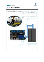
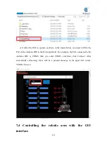
Note that the arm is still connected to the computer with the USB cable.
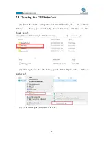
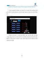
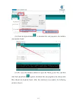
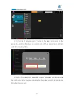
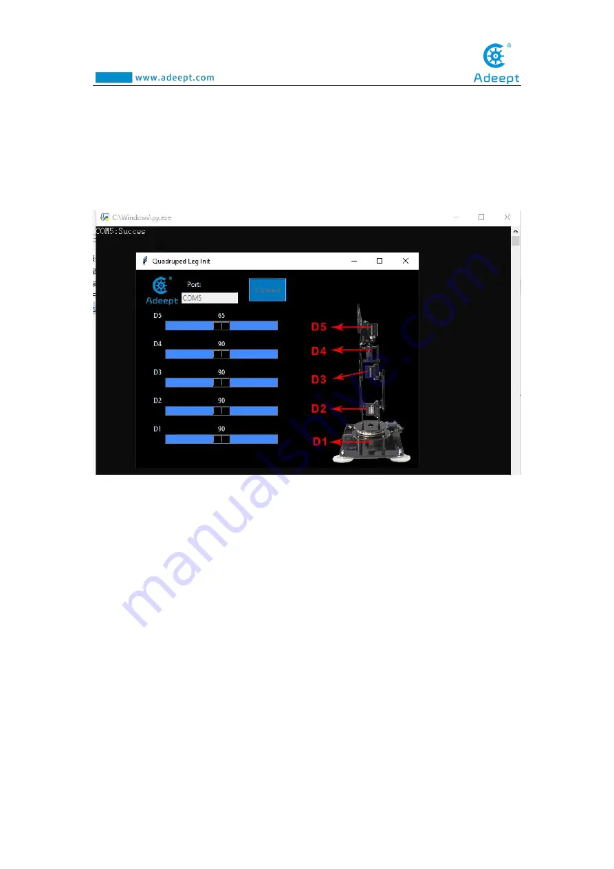
1. In the opened GUI interface, the left area is to control the movement of the
servo D1~D5, and the right area is the structure diagram of the servo of the robotic
arm.
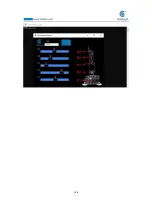
2. When you need to control the robotic arm, you can slide the slider
corresponding to the servo in the left area to control the movement of the robotic arm.
When a certain position is slipped, a data will be displayed on the slider, this data
represents the angle.
Содержание Robotic Arm
Страница 1: ...1...
Страница 33: ...30 9 Running effect is as follow...
Страница 70: ...67 Effect diagram after assembling Assemble the following components M3 8 Screw x4 M3 30 Nylon Standoff x4...
Страница 74: ...71 SERVO of number 5 4 2 1 3...
Страница 86: ...83 Effect diagram after assembling...
Страница 95: ...92 40mm 60mm 66 5mm 65mm 13mm 70mm...
Страница 99: ...96...
Страница 111: ...108...
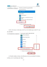
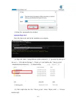
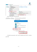
Страница 117: ...114 6 Click More apps then click OK 7 Slide the mouse down click Look for annother app on this PC and then click OK...
Страница 137: ...134...
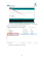
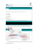
Страница 154: ...151 7 the library file controlP5 needs to be added...
Страница 156: ...153 9 Click Run 10 Running effect is as follow...
Страница 164: ...161...
Страница 181: ...178...
Страница 182: ...179...


