background image

ADCP-61-819 

 Issue 1 

 July 2000

Page 2

© 2000, ADC Telecommunications, Inc.

1.1 Graphic User Interface – S

WATCH

TM

 Switch Monitoring Software

The S

WATCH

TM

 GUI software for the Redundant Amplifier Switch provides continuous remote

monitoring of the switch and associated systems. It is designed for Windows

TM

95/98/NT/2000systems with a 133 MHz (or faster) Pentium

TM

 processor. See Section 4.

2

DESCRIPTION

This section provides functional, physical, and technical descriptions of the RDS-2 Redundant
Amplifier Switch.

2.1 Functional Description

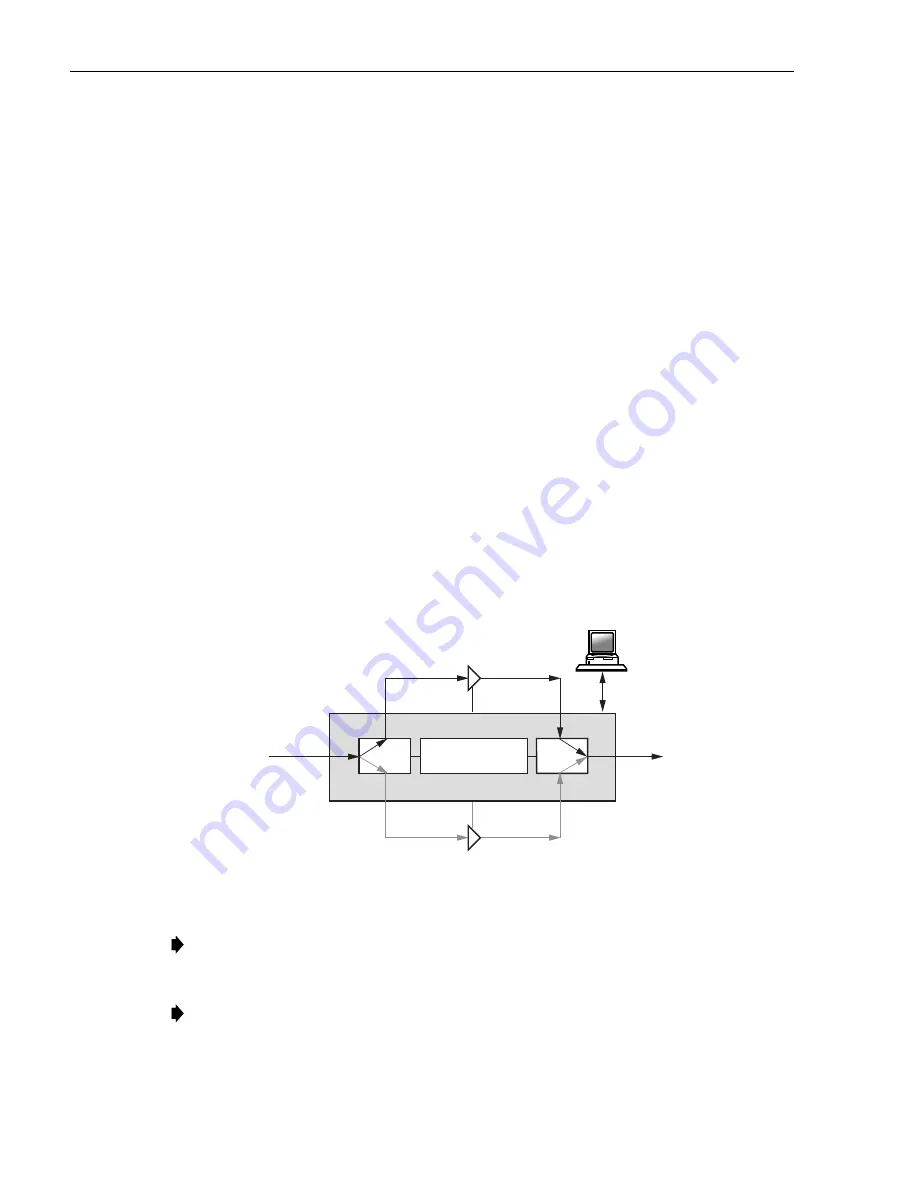
Figure 2

 is block diagram for the redundant amplifier switch. Both the RF input and output

signals are applied to a coupler that routes a small portion of the signal through an analog level
detection circuit and an analog-to-digital converter to the logic and control circuits. Other inputs
to the logic and control circuits include the SWITCHING THRESHOLD, GAIN TRIP LEVEL
(2 to 7 dB down from the amplifier reference level), Primary AMP SELECT, and the
NORMAL/CALIBRATE controls in the S

WATCH

TM

 software (see Section 4). When triggered by

a Primary amplifier gain failure, the logic and control circuits switch on input power to the
Backup amplifier, then, after a short delay, the RF In and RF Out signals are also switched over
to the Backup amplifier (total elapsed time equals approximately 50 msec). After successfully
switching to the Backup amplifier, input power to the Primary amplifier is turned off.

RF OUTPUT

RF INPUT

RF

RDS-2

A

A

B

B

RF

A INPUT

POWER

POWER

PORT 1

PORT 2

MICROPROCESSOR

CONTROL

PRIMARY

AMP

COMPUTER
MONITOR &

ALARM

SYSTEM

B INPUT

A OUTPUT

B OUTPUT

STANDBY

AMP

10141-A

Figure 2. Redundant Amplifier Block Diagram

Note: 

Single or


dual failure status will cause an alarm condition and close the alarm contacts.

Future revisions of the S

WATCH

TM

 software will provide increased programmability of alarm

conditions.

Note: 

Loss of signal status, defined as a loss of input RF signal to the RDS-2, does not

cause an alarm contact closure since the failure is in the network upstream of the RDS-2.
However, the loss of signal condition is indicated on the front panel of the Redundant
Amplifier Switch and through the S

WATCH

TM

 monitoring software.

Содержание RF Worx RDS-2

Страница 1: ...RDS 2 Redundant Amplifier Switch RF Worx Signal Protection User Manual ADCP 61 819 Issue 1 July 2000 1080155 Rev A 15026 A ...

Страница 2: ...ontents without prior notice In no event shall ADC be liable for any damages resulting from loss of data loss of use or loss of profits and ADC further disclaims any and all liability for indirect incidental special consequential or other similar damages This disclaimer of liability applies to all products publications and services during and after the warranty period This publication may be verif...

Страница 3: ...t Amplifier Switch Installation 6 3 2 Connecting the Redundant Amplifier Switch to a Computer 8 3 3 Alarm Wiring 8 3 4 220 too 240 VAC Operation 9 3 5 RF and Power Cables 10 3 6 The Setup Button 10 4 OPERATION SWATCH TM GRAPHIC USER INTERFACE 11 4 1 System Requirements 11 4 2 Installation 11 4 3 Graphic User Interface GUI Overview 12 4 4 Configuring the Program 14 4 5 Program Operation 29 4 6 Syst...

Страница 4: ...ADCP 61 819 Issue 1 July 2000 Preface Page iv 2000 ADC Telecommunications Inc ...

Страница 5: ...onishments in the form of Dangers Warnings and Cautions must be followed at all times These warnings are flagged by use of the triangular alert icon seen below and are listed in descending order of severity of injury or damage and likelihood of occurrence Danger Danger is used to indicate the presence of a hazard that will cause severe personal injury death or substantial property damage if the ha...

Страница 6: ... located on the front panel of the switch An RS 485 interface provides amplifier calibration data i e date and time and operating failure status to a Windows 95 98 NT 2000 personal computer PC equipped with SWATCHTM switch monitoring software and appropriate interface cards If the RF input to the primary amplifier falls below a detectable level the switch sends a Loss of Signal LOS alarm to the PC...

Страница 7: ... CALIBRATE controls in the SWATCHTM software see Section 4 When triggered by a Primary amplifier gain failure the logic and control circuits switch on input power to the Backup amplifier then after a short delay the RF In and RF Out signals are also switched over to the Backup amplifier total elapsed time equals approximately 50 msec After successfully switching to the Backup amplifier input power...

Страница 8: ... failure condition to minimize service degradation interruption 2 2 Physical Description Figure 3 shows the front panel of the Redundant Amplifier Switch The parts are identified by letter and include a brief description A B C D E F 15027 A Figure 3 Front Panel of the Redundant Amplifier Switch LETTER NAME DESCRIPTION A Amplifier Input Status LEDs Green When lit shows the active amplifier B Amplif...

Страница 9: ...ack frame B Setup Button Calibrates the unit C BNC F Type Connectors Connects the unit to network equipment D RS 485 Receptacles Input and output for personal computer with SWATCHTM switch monitoring software interface cables E Terminal Block Alarm and 48V battery power DC power connections F 24V VDC Power Provides 24V VDC power in for power supplies 1 and 2 left and 24V switched power out for Amp...

Страница 10: ...Typical at 750 MHz Composite Triple Beat CTB 67 dBc min 110 channels Composite Second Order CSO 67 dBc min 110 channels Total Power dBm 35 dBm to 15 dBm Calibration Range 26 dBm to 6 dBm Switching Time Return Delay 50 milliseconds maximum 15 seconds default Adjustable from 1 second to 4 minutes Switch action on power failure Retain position Calibration data retained for 1 week minimum Detection Po...

Страница 11: ...ork rack or equivalent Panel dimensions are shown in the front and top views in Figures 7 and 8 on page 7 1 At the designated rack location align the mounting holes in the switch mounting ears with the threaded holes in the rack then mount the redundant switch on the rack with four 12 24 screws See Figure 5 15029 A Figure 5 Installing the Redundant Switch in Rack 2 Using AWG 18 or larger stranded ...

Страница 12: ...BER 15030 A Figure 6 Rear View of the Redundant Amplifier Switch 1 25 IN 3 18 CM 1 75 IN 4 45 CM 18 31 IN 46 51 CM 18 98 IN 48 21 CM 15031 A Figure 7 Front View of the Redundant Amplifier Switch with Dimensioned Mounting Ears 17 20 IN 43 69 CM 15032 A Figure 8 Top View of Redundant Amplifier Switch ...

Страница 13: ...02 A Figure 9 Daisy Chained Redundant Amplifier Switch Units 3 3 Alarm Wiring Connect two 22 26 AWG wires to the alarm terminals at the rear panel labeled ALARM NO normally open and C common See Figure 10 Connect the other ends of the wires to the alarm panel at the installation location NO C SPARE ALARM IN 2 VDC 48 IN 1 14956 A Figure 10 Terminal Block for Alarm and DC Power Connections Warning T...

Страница 14: ...the power inlet module door from the right side using a small screwdriver or equivalent 3 Remove the fuse module using a small screwdriver or equivalent 4 Rotate the fuse module 180 so that the text 230V will show through the power inlet module window when the door is closed 5 Place the fuse module back into the power inlet module making sure that the fuse module is seated properly 6 Close the pow...

Страница 15: ... rear panel of the switch or if they are powered by direct current connect them to the corresponding DC output connections on the terminal block Figure 12 at the rear of the switch 3 Perform any optional steps required for your system 4 Upon initial power up the front panel LED should be lit indicating that the internal power supply is operational 3 6 The Setup Button The setup button is used to c...

Страница 16: ...r or faster and at least 16 MB of RAM 32 MB recommended Note Windows 2000 Professional requires at least 64 MB of RAM 4 2 Installation Insert the SWATCH TM disk into your computer s CD ROM drive The installation program should begin automatically If the installation program fails to start perform the following procedure 1 Click Start on the windows taskbar 2 Select Run from the start menu 3 Enter ...

Страница 17: ...f description of each term follows Figure 13 TREE PANE EVENT PANE UNIT PANE MENU BAR STATUS BAR DISPLAY BAR Figure 13 SWATCH TM GUI Menu Bar Opens drop down menus that house program options Tables 3 through 6 on the next page contain a description of each menu Tree Pane Displays either the Site Map or Unit List Status Bar If enabled displays tips mouse pointer references and mail reporting results...

Страница 18: ...ences Opens the global Preferences dialog box 1 2 3 4 A list of the most recently opened files Exit Closes the program Table 4 View Menu Status Bar Displays or hides the Status Bar Unit List Displays the units by serial number in the Tree Pane Site Map Displays the Site Map tree in the Tree Pane Default Display Unit Status Displays the current unit port power and failure status in the Unit Pane Un...

Страница 19: ...ch Help Opens the Swatch Help program Help Topics Displays an index of help topics What s This Opens a pop up Help program Click on an item in the program and you will see a pop up box with a brief description of that item About Displays the version number of this application 4 4 Configuring the Program Upon initial launch after installation a setup wizard Figure 14 will guide you in a step by ste...

Страница 20: ...led description of the Preferences command however the same dialog descriptions apply to the setup wizard 4 4 1 Using the Preferences Command This dialog sets up global preferences for the program Open the preferences by using the drop down menu as shown in Figure 15 Right click the Tree Pane or the Event Pane to access the Preferences command ...

Страница 21: ... specify a particular site map file to open when the program is launched The default setting is no site map Event Log Specifies the file to which the events for a particular database site map are logged The default setting is to save all events to the event log named Swatch log This box must be checked to save new events to the event log or to see recorded events displayed in the event pane Figure...

Страница 22: ...B Max Threshold Check these boxes to enable the creation of maximum threshold values for side A and or B Max Threshold Enter the system s maximum threshold value if threshold adjustment enabled in this edit box Min Threshold Enter the system s minimum threshold value if threshold adjustment enabled in this edit box Enable Recalibration Check this box to enable system recalibration Return Delay Aft...

Страница 23: ...of all channels in the system Show Average Channel Level dBmV Click this radio button to display the average power level for each channel in the system Enter the combined channel count in the edit box Show Average Channel Level Between Split Linked Ports Click this radio button to display the average power level of all channels in a split linked system Enter the channel count for Port 1 in the upp...

Страница 24: ... your PC Those ports determined to be available will have a check placed next to them in the COM Port Check Boxes Note A dialog box will appear when the program has determined that a port is not available Figure 18 COM Ports Tab Scan Tab Select this tab Figure 19 for the input and selection of scanning parameters Status Scan The status scan determines if an event e g an alarm has occurred in all d...

Страница 25: ...ated assigned to parent sites within the tree The text box displays the scan period in milliseconds Select the check box to start the discovery scan when the program is launched no site map is required Note By default the check box is initially left blank Note Only RDS 2 units will be found RDS 1 units will be ignored by the discovery process and will not be detected Figure 19 Scan Tab Reporting T...

Страница 26: ...this box Message Enter the text of the message in this box The message may contain tokens that will be converted based on the event being reported Tokens consist of the percent character followed by a zero or more decimal digits followed by a character listed below The digits determine the maximum width of the substituted result taking the right most characters A width of four will convert ABC123 ...

Страница 27: ...it in the unit s sub tree This will change the Unit Properties screen to that of the first unit Next Unit Click this button to move to the next unit in the unit s sub tree This will change the Unit Properties screen to that of the next unit Use this to step through all units in the Site Map Serial Number The serial number of the RDS unit is entered either manually or automatically see Section 4 4 ...

Страница 28: ...will search all available COM ports for new units by forcing the Discovery Scan to take place Communication Errors Clicking the Clear Errors button clears a counter maintained for each unit When a unit does not respond to a request even after several retries this is one communication error This results in a warning Event Log entry and the port icon turns yellow If after several attempts the count ...

Страница 29: ...Preferences Allows RDS2 units to be individually configured Note Switching from global to local will restore the former local settings for that specific RDS2 unit Enable Thresholds Enables the local threshold setting and enables disables calibration for this unit Note To adjust threshold settings both the local and global settings must be enabled Set Power Units Sets the local power units This ove...

Страница 30: ...ss the Unit Status command Serial Number Displays the unit s serial number Description Displays user input description of the unit Failure History To be implemented in a future release This screen is covered in greater detail in Section 4 6 System Monitoring Figure 23 Redundant Amplifier Unit Status Screen 4 4 4 Creating a New Database Create a new database by using the File New command from the m...

Страница 31: ...nit Properties view Figure 21 Right click the Tree Pane or the Event Pane to access the Site Map Properties command 2 Select a Port tab 3 Select Edit Sites The Manage Site Map dialog Figure 25 will appear Figure 25 Manage Site Map Dialog 4 In the Parent drop down menu select an existing site as the parent of the new site If the parent is blank the new site will be at the uppermost site position 5 ...

Страница 32: ...lly Adding a Unit Manually Perform the following procedure to manually add a unit to the program 1 Use the View Unit Properties menu command to switch the Unit Pane to the Unit Properties view Figure 21 2 Enter the serial number and function of the unit 3 Select the Locate tab and enter the COM port 4 Click on the port tab s and select a site to which the unit port will be assigned 5 Select the Ad...

Страница 33: ...each new unit is found you may be prompted to accept the unit before it is added to the program 4 4 7 Moving a Unit Port to Another Site Perform the following procedure to move a unit or individual port to another site in the Site Map 1 Select the unit or port you wish to move by left clicking on that item in the Unit List Site Map Use the View Unit Properties menu command to switch the Unit Pane ...

Страница 34: ...controlled in the Unit Pane via either a Properties display or a Status display The unit and port properties are saved in the Site Map file even when not enabled for use 4 5 2 Scanning and Communication Errors The SWATCH TM program scans the system at an interval established in the Preferences dialog During the scanning process the program ensures that each unit is connected to its respective COM ...

Страница 35: ... Site Map The Unit List displays all units in the system in numerical order Figure 29 Figure 29 Unit List The unit status is displayed using a coloring scheme detailed in Table 7 By looking at the Site Map or Unit List it is easy to find any units that are not functioning normally ...

Страница 36: ...ation would otherwise not be a failure but is too high or too low by more than the Minor Threshold the power meter is not green on green but magenta on green The Site Map reports any errors up through the tree with each subsequent superior node appearing in the color that represents the most serious condition found in the inferior nodes The Unit List displays errors on a unit by unit basis 4 5 4 E...

Страница 37: ...des the option of logging normal events warnings and or failures Note This filter does not control what is viewed in the Event Log See Section 4 5 5 Display Filter Figure 31 Capture Filter 4 5 6 Display Filter This dialog Figure 32 allows the user to choose which events are displayed in the Event Log Pane The dialog provides the option of displaying normal events warnings and or failures as well a...

Страница 38: ...or only those units in the selected Site Map sub tree For example if a particular unit appears in yellow Figure 33 in the Site Map and you would like to view the events for that unit only select Follow Site Map then click on the unit in question and the information for that unit will be displayed in the Event Log Pane Figure 33 Follow Site Map Example ...

Страница 39: ...if there is an acceptable power level on the opposite side Calibrate Click this button to calibrate the associated side if enabled Serial Number Displays the unit s serial number Description Displays user input description of the unit Failure History Displays a list of unit failures 4 6 1 Power Meters The Power Meters provide an analog rendering of the unit s status Figure 34 provides a reference ...

Страница 40: ...dy for finding the calibration figure as well as verifying the min max thresholds Table 8 Power Meter Ranges and Colors Calibration Level Maximum Threshold Exceeded Failure Red on Red Calibration Level Minor Threshold OK Magenta on Green Calibration Level OK Green on Green Calibration Level Minor Threshold OK Green on Green Calibration Level Minimum Threshold Exceeded Failure Red on Red Figure 35 ...

Страница 41: ... records that signal as the optimal signal strength for normal operation Capture Filter Dialog that allows the user to choose which events are written to the Event Log file COM Port Serial RS 232 Input Output port on a PC Linked to an RDS unit s RS 485 communications port via serial cables and an RS 232 to RS 485 converter Discovery Scan Scans all defined COM ports and will detect any new or missi...

Страница 42: ...lay of the programs interpretation of what is occurring in the system This is a graphical rendering that allows the user to monitor how each unit port is performing It should be noted that the decision to switch to a backup side is made by the unit itself the software is only used for monitoring purposes Preferences A series of screens used to establish global program settings Return Delay After a...

Страница 43: ...ifier switch are minimal consisting merely of periodic cleaning 5 1 Preventive Maintenance The outside of the Redundant Amplifier switch should be cleaned during routine headend equipment maintenance 5 2 Fuse Replacement Caution For continued safe operation and to reduce the risk of fire replace fuses with the same type and rating ...

Страница 44: ... phone number in the United States is 1 952 946 1400 Contents herein are current as of the date of publication ADC reserves the right to change the contents without prior notice In no event shall ADC be liable for any damages resulting from loss of data loss of use or loss of profits and ADC further disclaims any and all liability for indirect incidental special consequential or other similar dama...

Страница 45: ...www adc com ...

Отзывы: