


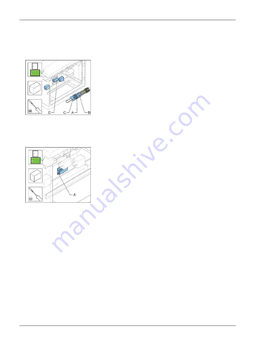
31. Connect the cables:
•
Fuses F1, F2 and F3 (A);
•
Over-voltage protection MOV (if present) (B);
•
Socket (if present) (C);
•
Three mains filters (D).
Connect heater cables
32. Slide thermo-retractable insulation sleeves on the cables;
33. Solder one cable on the connection point (A) on both sides of the heater;
34. Slide the insulation sleeve over the solder points.
Connect - 3
35. Install the rail (A).
36. Install the two screws (B) .
37. Connect the cables:
•
Power input terminals L1, L2 and L3 and protective earth terminals (A);
•
FCU 1 PCB (connectors P7, P6 and P5) (B);
•
FCU 2 PCB (connectors P6 and P5) (C);
•
FCU 3 PCB (connector P5) (D);
•
DC power supply (input wires) (E);
•
Local bus connection board (F);
•
Multiwire PCB (J1) (G).
38. Bind the cables. Use cable binders.
39. Install the cover.
40. Close the cabinet door.
Flashing System Maintenance
Maintenance
50
Copyright
©
ADB Safegate, All Rights Reserved
Содержание FCU-1-in-1
Страница 2: ......
Страница 8: ...Flashing System Maintenance TABLE OF CONTENTS viii Copyright ADB Safegate All Rights Reserved ...
Страница 18: ...Flashing System Maintenance Safety 8 Copyright ADB Safegate All Rights Reserved ...
Страница 23: ...3 2 2 FCU 3 UM 4019_AM02 620e Rev 3 0 2020 05 12 13 Copyright ADB Safegate All Rights Reserved ...
Страница 28: ...Flashing System Maintenance Introduction 18 Copyright ADB Safegate All Rights Reserved ...
Страница 42: ...Flashing System Maintenance Commissioning 32 Copyright ADB Safegate All Rights Reserved ...
Страница 64: ...Flashing System Maintenance Maintenance 54 Copyright ADB Safegate All Rights Reserved ...
Страница 74: ...Flashing System Maintenance Checks and measurements 64 Copyright ADB Safegate All Rights Reserved ...
Страница 102: ...FCU 3 Flashing System Maintenance PCB drawings and settings 92 Copyright ADB Safegate All Rights Reserved ...
Страница 106: ...Flashing System Maintenance Technical data 96 Copyright ADB Safegate All Rights Reserved ...
Страница 110: ......