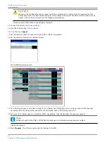
20. Check the message windows that appears on the screen.
•
Layout OK” means that the new layout was sent successfully.
•
“Layout Not OK” means that you must check the layout and the dip-switch settings again.
Check if the equipments are on-line
21. Go to section Flasher data .
22. Press Status .
23. Check if the status of the LMC and all flasher heads is Online .
24. If this is not the case, check the power supply to all equipment cabinets
•
The power supply to all equipment cabinets;
•
The position of the door switches;
•
The binary addresses on the FCU PCBs;
•
The local bus communication cables.
Define the flashing mode
Set the flashing mode
UM-4019_AM02-620e, Rev. 3.0, 2020/05/12
25
Copyright
©
ADB Safegate, All Rights Reserved
Содержание FCU-1-in-1
Страница 2: ......
Страница 8: ...Flashing System Maintenance TABLE OF CONTENTS viii Copyright ADB Safegate All Rights Reserved ...
Страница 18: ...Flashing System Maintenance Safety 8 Copyright ADB Safegate All Rights Reserved ...
Страница 23: ...3 2 2 FCU 3 UM 4019_AM02 620e Rev 3 0 2020 05 12 13 Copyright ADB Safegate All Rights Reserved ...
Страница 28: ...Flashing System Maintenance Introduction 18 Copyright ADB Safegate All Rights Reserved ...
Страница 42: ...Flashing System Maintenance Commissioning 32 Copyright ADB Safegate All Rights Reserved ...
Страница 64: ...Flashing System Maintenance Maintenance 54 Copyright ADB Safegate All Rights Reserved ...
Страница 74: ...Flashing System Maintenance Checks and measurements 64 Copyright ADB Safegate All Rights Reserved ...
Страница 102: ...FCU 3 Flashing System Maintenance PCB drawings and settings 92 Copyright ADB Safegate All Rights Reserved ...
Страница 106: ...Flashing System Maintenance Technical data 96 Copyright ADB Safegate All Rights Reserved ...
Страница 110: ......

