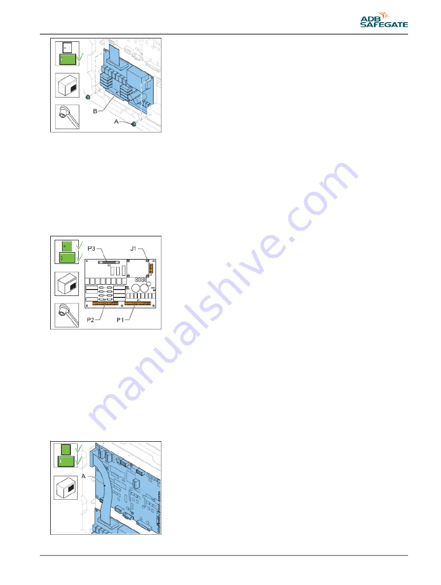
Connect
7. Connect the cables to the connectors:
•
Power supply to J1;
•
LMC to P3;
•
Input and output signal connectors to P1 and P2.
8. Check the remote control functions.
9. Configure the flashing system. See §
10. Close the cabinet door.
5.2.7 Multiwire cable
1. Make sure that all power to the equipment is OFF. See §
Prepare: Switch OFF power supply
.
2. Disconnect the flat multiwire cable (A) from the connector P5 of the LMV PCB and P3 of the multiwire PCB.
3. Install the new multiwire cable (A).
4. Connect the multiwire cable (A) to the connector P5 of the LMC PCB and P3 of the multiwire PCB.
5. Close the cabinet door.
6. Check the remote control functions.
7. Close the cabinet door.
UM-4019_AM02-620e, Rev. 3.0, 2020/05/12
41
Copyright
©
ADB Safegate, All Rights Reserved
Содержание FCU-1-in-1
Страница 2: ......
Страница 8: ...Flashing System Maintenance TABLE OF CONTENTS viii Copyright ADB Safegate All Rights Reserved ...
Страница 18: ...Flashing System Maintenance Safety 8 Copyright ADB Safegate All Rights Reserved ...
Страница 23: ...3 2 2 FCU 3 UM 4019_AM02 620e Rev 3 0 2020 05 12 13 Copyright ADB Safegate All Rights Reserved ...
Страница 28: ...Flashing System Maintenance Introduction 18 Copyright ADB Safegate All Rights Reserved ...
Страница 42: ...Flashing System Maintenance Commissioning 32 Copyright ADB Safegate All Rights Reserved ...
Страница 64: ...Flashing System Maintenance Maintenance 54 Copyright ADB Safegate All Rights Reserved ...
Страница 74: ...Flashing System Maintenance Checks and measurements 64 Copyright ADB Safegate All Rights Reserved ...
Страница 102: ...FCU 3 Flashing System Maintenance PCB drawings and settings 92 Copyright ADB Safegate All Rights Reserved ...
Страница 106: ...Flashing System Maintenance Technical data 96 Copyright ADB Safegate All Rights Reserved ...
Страница 110: ......


