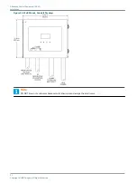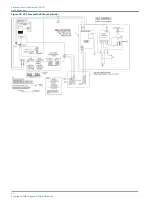
The Combo Box-Mount must be flush against a wall as in
, or on U-channels supporting all four
corners of the enclosure. See
Figure 16: Combo Box-Mount, External View
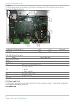
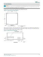
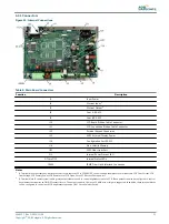
Figure 17: Combo Box-Mount, Internal View
Note
The ACE2 enclosure is designed to be replaced easily without having to remove any of the mounting hardware. Follow
these instructions:
1. Position the enclosure flush on its mounting surface.
Level the enclosure and then open the lid and mark or transfer punch the location of the 3/8’’ diameter holes in each of
the corners of the enclosure. Refer to
.
2. Remove the ACE2 unit, drill out the marked holes, and insert anchor hardware as required.
DO NOT DRILL THOUGH THE BOX to keep drilling chips and debris from falling into the enclosure.
3. Carefully open the lid of the enclosure.
Use ¼-20 x 1.0-inch long screws, flat washers, and lock washers to fasten the enclosure to the wall or to rails.
4. Mount the enclosure using the top two holes then install the hardware for the bottom two holes.
5. Attach all conduits to the bottom or to the top access plate ONLY as seen in
.
6. Protect ALL electronic equipment in the ACE2 enclosure while installing conduit to the BOTTOM or to the TOP access
plate.
Advanced Control Equipment (ACE2)
Installation
24
Copyright
©
ADB Safegate, All Rights Reserved
Содержание ACE2
Страница 1: ...Advanced Control Equipment ACE2 User Manual 96A0357 Rev G 2019 11 08 ...
Страница 2: ......
Страница 6: ...Advanced Control Equipment ACE2 TABLE OF CONTENTS vi Copyright ADB Safegate All Rights Reserved ...
Страница 10: ...Advanced Control Equipment ACE2 Advanced Control Equipment 4 Copyright ADB Safegate All Rights Reserved ...
Страница 18: ...Advanced Control Equipment ACE2 Introduction 12 Copyright ADB Safegate All Rights Reserved ...
Страница 42: ...Advanced Control Equipment ACE2 Parts 36 Copyright ADB Safegate All Rights Reserved ...
Страница 46: ......

