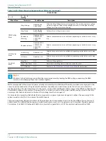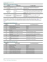
Table 2: ACE2 Stand-Alone Configuration Short Reference (continued)
Button Action
2 ↓ , 3
2 ↓ , 3 ←, 1
modify
Menu Item
Parameter
Possible value
Description
IRMS Config
Menu
Meg Voltage
Disabled, 50V,
500V, 1000V
Select the Meg Voltage based on the regulator. The smaller regulators voltage
protection triggers if higher Meg Voltages are used, but the higher the Meg
Voltage, the more accurate the reading.
Meg Period
5min, Hourly,
Daily, Weekly
Set how often to Meg the field circuit
Resistance
Warning
Disabled, 100K,
300K,1M, 3M,
10M, 30M,
100M
Select a resistance value to be notified at depending on the field circuit, it may
vary.
Resistance Alarm
Disabled, 100K,
300K,1M, 3M,
10M, 30M,
100M
Select a resistance value to be notified at depending on the field circuit, it may
vary.
LOM Config
Menu
LO Warning
Disabled, 1-15
Select a Lamp out value to be notified at depending on the field circuit, it may
vary.
LO Alarm
Disabled, 1-15
Select a Lamp out value to be notified at depending on the field circuit, it may
vary
Command
Menu
Meg Now
N/A
Perform a Meg right now
Meg Timer Reset
N/A
Reset the current Meg timer to start over with the count.
LO Calibration
N/A
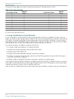
See
Lamps-Out Calibration for Stand-Alone Mode
Exit
N/A
N/A
Note
VA refers to the Volt-Amps in an airfield load and is measured by reading the RMS voltage, measuring the RMS
current, and multiplying these two numbers together.
Watts corresponds to the amount of power actually consumed by an airfield load. These two numbers are only equal in the
case of a purely resistive load. In systems with reactance (capacitance or inductance), power from the source enters the
reactive portions of the load, and returns to the source, un-used. This additional unused energy is the difference between the
VA and Watts delivered to a system. The power factor of a load is the ratio of the power (watts) used by a load, to the volts
and amps (VA) that are delivered to the load. This is always less than or equal to 1.
It is important to remember that all electrical components in a power system are designed to deliver the necessary VA the
system needs in order for it to consume the watts it needs.
CCR sizes are actually designed to deliver a kVA value because it is impossible to account for the different power factors in
airfield loads. If an airfield load has open-circuited transformers, signs, etc. it requires more VA to deliver the watts needed.
For instance, if a 30kW CCR delivered 30kVA into a load with a power factor of 0.5 the resultant watts would be 15kW.
Advanced Control Equipment (ACE2)
Modes of Operation
14
Copyright
©
ADB Safegate, All Rights Reserved
Содержание ACE2
Страница 1: ...Advanced Control Equipment ACE2 User Manual 96A0357 Rev G 2019 11 08 ...
Страница 2: ......
Страница 6: ...Advanced Control Equipment ACE2 TABLE OF CONTENTS vi Copyright ADB Safegate All Rights Reserved ...
Страница 10: ...Advanced Control Equipment ACE2 Advanced Control Equipment 4 Copyright ADB Safegate All Rights Reserved ...
Страница 18: ...Advanced Control Equipment ACE2 Introduction 12 Copyright ADB Safegate All Rights Reserved ...
Страница 42: ...Advanced Control Equipment ACE2 Parts 36 Copyright ADB Safegate All Rights Reserved ...
Страница 46: ......


