9
ActronAir
is constantly seeking ways to improve the design of its products, therefore specifications are subject to change without notice.
Copyright © 2022 Actron Engineering Pty. Ltd.
CP05 & CP10 CONTROL INTERFACE INSTALLATION GUIDE
RX+ / TX+
19
RX- / TX-
20
+Vdc
21
GND
22
NOTE:
Use these terminals for
Tri-Capacity models.
Electrical Panel
Control Interface # 2
Remote Mimic Control
CP10 or CP05
(
To be Purchased Separately
)
CP10 Control Interface # 1
Master Control
(
Supplied & Fitted as Standard
)
input 24V +10% -15% 50-60Hz / 28-36V
max power: 28W/20W
BMS Card
J11 BMS2
GND
Tx/Rx
J14pLAN
Vout
J9 FBus1
J10
J15
J12
1
U8
U9
U10
+V
dc
+5VR
GND
J5
DI7H
DI7
DI7C
DI8
DI8H
J25
GND
Y1
Y2
Y3
J6
U1
U2
U3
GND
J2
D11
D12
D13
D14
GND
J7
U6
U7
+V
dc
+5VR
GND
J4
46
U5
+V
dc
+5VR
GND
J3
NO1
NC1
NC1
J16
Out3
C2
J18
Out4
C2
J19
Out5
C2
J20
NO6
C6
J22
NO7
C7
J23
NO8
C8
J24
C2
V-IN
J21
Out2
C2
J17
C11
NO11
NO12
NO13
C11
J28
NO9
C9
NC9
NO10
C10
NC10
J27
J8
2
Y4
Y5
U11
GND
U12
GND
D9
D10
DI9C
J26
G
G0
J1
cm
100
®
J13
GND
J29FBus2
Tx/Rx
RX+ / TX+
11
RX- / TX-
12
+Vdc
13
GND
14
6 Core (3 Pair) Twisted Pair 7/0.20 (AWG24)
Shielded Data Cable 200 Max. Length - Field Scope
(
Installer to Provide
)
6 Core Flat 7/0.12 (AWG28) Telephone Cable
50m Max. Length - Field Scope
(
Installer to Provide
)
-- or --
CM100 Controller
(
Supplied & Fitted as Standard
)
Esc
Prg
Return Temp:
23.7
o
C
16.5
o
C
Supply Temp:
Comp
Rev Vlv
9:30 Unit: On Auto
Esc
Prg
Return Temp:
23.7
o
C
16.5
o
C
Supply Temp:
Comp
Rev Vlv
9:30 Unit: On Auto
*
CP05 or CP10 may be used as Secondary Control Interface.
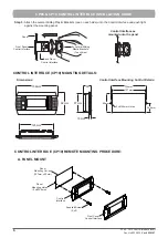
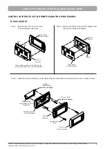
Refer Control Interface mounting procedure on pages 6-8.
DUAL CONTROL CONNECTION INSTALLATION
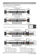
1.0 Components Required
• 1- Pc Control Interface
(
Secondary Control Interface to be Purchased Seperately
)
•
1- Pc 6 Core Flat 7/0.12 (AWG28) Telephone Cable for lengths up to 50m (
Installer to Provide
)
•
1- Pc 6 Core (3 Pair) Twisted Pair 7/0.20 (AWG24) Shielded Data Cable for lengths up to 200m
(
Installer to Provide
)
•
1- Pc 4-Way Connector Block (as required for Tri-Capacity Units
-
Installer to Provide
)
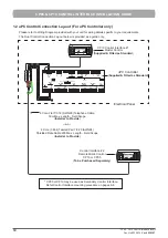
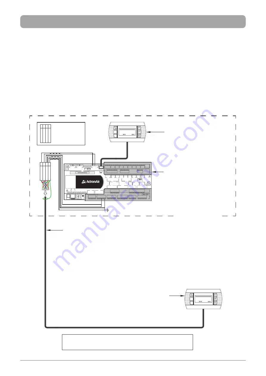
1.1 Dual Control Connection Lay-out (For CM100 Controller Only)
Please refer to Wiring Diagram provided with your unit for wiring details specific to your requirements.
The Dual Control Connection Lay-out below is provided as a guide only.
Содержание CP05
Страница 13: ...THIS PAGE WAS INTENTIONALLY LEFT BLANK ...
Страница 14: ...THIS PAGE WAS INTENTIONALLY LEFT BLANK ...
Страница 15: ...THIS PAGE WAS INTENTIONALLY LEFT BLANK ...

