12
CP05 - CP10 Control Interface Insert
Doc. No.0525-035
Ver. 6 220307
CP05 & CP10 CONTROL INTERFACE INSTALLATION GUIDE
8
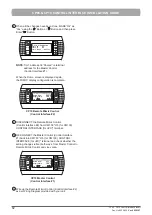
When all the changes have been done, MAKE “Ok” as
“Yes” using the “ ” Button or “
” Button and then press
Enter “
” Button:
Esc
Prg
P: 01 Adr Priv/Shared
Trm1 32 Sh
Trm2 31 Sh
Trm3 None - - Ok?Yes
NOTE
: Trm1 address 32 “Shared” is terminal
address for the Master Control
(Control Interface #1).
When the Home screen is displayed again,
the MIMIC display configuration is complete.
Esc
Prg
Return Temp:
23.7
o
C
16.5
o
C
Supply Temp:
Comp
Rev Vlv
9:30 Unit: On Auto
CP10 Remote Mimic Control
(Control Interface #2)
9
DISCONNECT the Remote Mimic Control
(Control Interface #2) from CM100 "J15 (for CM100),
CONTROL INTERFACE (for uPC)" terminal.
10
RE-CONNECT the Master Control (Control Interface
#1) back into CM100 "J15 (for CM100), CONTROL
INTERFACE (for uPC)" terminal and check whether the
setting changes reflect both ways, from Master Control to
Remote Mimic Control and vice versa.
Esc
Prg
Return Temp:
23.7
o
C
16.5
o
C
Supply Temp:
Comp
Rev Vlv
9:30 Unit: On Auto
CP10 Master Control
(Control Interface #1)
10
Wire up the Remote Mimic Control (Control Interface #2)
as per Wiring Diagram provided with your unit.
Содержание CP05
Страница 13: ...THIS PAGE WAS INTENTIONALLY LEFT BLANK ...
Страница 14: ...THIS PAGE WAS INTENTIONALLY LEFT BLANK ...
Страница 15: ...THIS PAGE WAS INTENTIONALLY LEFT BLANK ...

