7
ActronAir
®
is constantly seeking ways to improve the design of it’s products, therefore specifications are subject to change without notice. Please check prior to purchase.
Copyright © 2016 Actron Engineering Pty. Ltd.
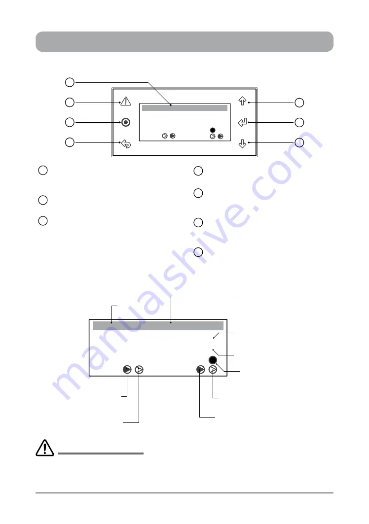
CONTROL INTERFACE FUNCTIONS
CONTROL INTERFACE FRONT VIEW
LCD Display
Displays the setting and operation
conditions (see menu page for details).
Alarm / Reset Button
Alarm Indication and Reset Button.
Program Button
To bring-up programming Main Menu
screen. (Display will revert back to
default screen after 5 minutes idle time
at any stage of programming).
1
2
3
ESC Button
To exit programming menu.
Scroll Up / Increment Button
To scroll up from existing menu or to
increase setting parameter.
Enter Button
To lock the selected menu or to enter
set parameters.
Scroll Down / Decrement Button
To scroll down from existing menu or to
decrease setting parameter.
4
5
6
7
SYSTEM DEFAULT SCREEN
Room T. :
23.7
o
C
o
C
Supply T. :
Comp
Rev Vlv
Defrost
10:20 Unit: Unit ON
3
4
2
1
6
5
7
Room T. :
23.7
o
C
o
C
Supply T. :
Comp
Rev Vlv
Defrost
10:20 Unit: OFF by KEY
Current Time
Unit Control Indicator
by Control Interface
Actual Room Air
Temperature
Reversing Valve 2
ON / OFF Indicator
Actual Supply Air Temperature
(Not Available)
Defrost Cycle
Indicator
Reversing Valve 1
ON / OFF Indicator
(Dark Filled arrow indicates ON)
Compressor 2
ON / OFF Indicator
(Dark Filled arrow indicates ON)
Compressor 1
ON / OFF Indicator
Other Unit Control Indicators:
• by Timeclock
• by 3rd Party
• by DRM
• by BMS
CP05
and
CP10
are two identical control interfaces with the same display and functions. The only differences
are the interface buttons and front case appearances.
CP05 is supplied as standard,
while
CP10
is supplied
as optional control interface for commercial range air conditioning systems. This manual covers operations
applicable to both control interfaces, however CP05 control interface features are shown for ease of illustrations.
IMPORTANT NOTES


