8
Troubleshooting Guide - Advance Split Ducted Unit
Doc. 9590-2015-03 Ver. 3 221111
Troubleshooting Guide
Advance Split Ducted Unit
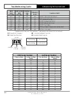
04.02. Expected Control Voltage On Communication Line - InZone Board (R-410A / R-32)
NOTES
• If COM1 (LED1) and COM2 (LED2) are blinking, communication is occurring.
• * Voltage sending between A-G and B-G are fluctuating, this means communication is occurring.
• Prior to measuring the control voltage ensure communication wires are properly connected to the CPU
board.
ZONE 8
ZONE 7
ZONE 6
ZONE 5
ZONE 4
ZONE 3
ZONE 2
ZONE 1
COM1
LED1
COM2
LED2
COM3
LED3
PWR
LED4
*VDC VALUES
UNO Board: 0.4 - 3 VDC
UNO Pro Board: 1 - 3 VDC
VDC*
VDC*
04.03. Expected Control Voltage On Communication Line - UNO Board Series (R-410A)
CONDENSER CPU BOARD
SMPS 240VAC/12VDC
FAN POWER 2
240V AC
FAN POWER 1
240V AC
A
A
N
N
FAN
CAP H
FAN
CAP M
FAN
CAP L
AMB
SENSOR
OUTPUT
0-10V G
REMOTE
ON/OFF
G 12V
+12V
COM
DRM3
COMP
DRM2
FAN
DRM1
HEAT
COIL
TEMP
HP
SENSOR
LP
SENSOR
HP
SW
LP
SW
RUN
FAULT
N PFC
N COMP
N PWM
N CCH
N REV
CO
M
LQD
HEAT
LQD
COOL
DLT
TEMP
SCT
TEMP
AUX 485
12V A B G
INDOOR 485
A B G
VSD 485
A B G
OCB
FUSE
250V AC 10 A
SLOW BLOW
SIZE 5 x 20mm
M
EN
U
E
N
T
ER
B
AC
K
DISPLAY
A
N
MAINS
POWER
AC/L
AC/N
V-
V+
COM 1
COM 2
COM 3
PWR
SW1
PROG
EXV
0
-10V
INP
UT
G
LED 1
LED 2
LED 3
A
0.4 - 3 VDC*
G
G
B
1 - 3.2VDC*
A
G
B
G
0.4 - 3 VDC*
1 - 3.2VDC*
FAN
CAP H
FAN
CAP M
FAN
CAP L


