background image

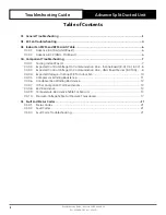
IMPORTANT NOTE:

Please read this manual carefully before installing or operating your air conditioning unit.

That’s better. That’s Actron.

ADVANCE
Split Ducted Unit

Troubleshooting Guide

Model Numbers

R-410A

R-32

CRV140S

CRV13AS

CRV160S

CRV15AS

CRV180S

CRV17AS

CRV160T

CRV13AT

CRV180T

CRV15AT

CRV210T

CRV17AT

CRV240T

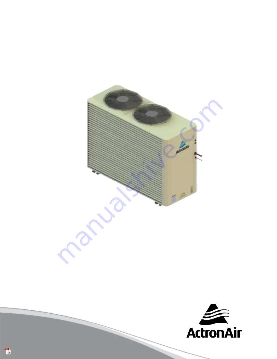
Model shown is R-410A

Содержание ADVANCE CRV13AS

Страница 1: ... or operating your air conditioning unit That s better That s Actron ADVANCE Split Ducted Unit Troubleshooting Guide Model Numbers R 410A R 32 CRV140S CRV13AS CRV160S CRV15AS CRV180S CRV17AS CRV160T CRV13AT CRV180T CRV15AT CRV210T CRV17AT CRV240T Model shown is R 410A ...

Страница 2: ... 04 02 Expected Control Voltage On Communication Line InZone Board R 410A R 32 8 04 03 Expected Control Voltage On Communication Line UNO Board Series R 410A 8 04 04 Expected Voltage InZone PCB To Indoor Fan 10 04 05 Compressor Winding Resistance 11 04 06 Condenser Fan Winding Resistance 12 04 07 Other Component Coil Resistances 13 04 08 EEV Resistance 13 04 09 Temperature Resistance Table For Sen...

Страница 3: ...outside of the operating range Reduce the total static pressure of the ductwork For example increase duct sizes reduce tight duct work bends or increase return air grille size The heat load is greater than the installation design Perform a heat load analysis on the conditioned space Turn any unused zones to the off position Windows or doors are open Close windows and doors in conditioned areas The...

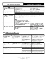
Страница 4: ...hed by a technician Consult the installer from whom you purchased the air conditioner No P Trap installed Re pipe drain with a P Trap Dry P Trap Contact the installer to carry out a general service and fill the P Trap 02 EC Fan Troubleshooting Fault Sequence of Events Possible Causes Remedies 1 Auto Mode is not available When scrolling through fan speeds Auto Mode is not selectable During commissi...

Страница 5: ...y cycle Refer to table below test points expected voltages To determine if the system may be suffering from excessive or insufficient static check PWM RPM values through the indoor unit dashboard on the Master Wall Controller If the RPM is at its maximum value and the PWM has not reached its requested value this indicates a high static Please refer to RPM Limits in Section 0 3 When switching off z...

Страница 6: ...60 EVV160S 42 58 77 EVV180S 50 69 99 EVV210S 43 61 82 EVV240S 44 62 84 Unit Model RPM Limits Low Medium High EVV140S 1150 1290 1390 EVV160S 1150 1290 1390 EVV180S 1150 1290 1390 EVV210S 1150 1350 1500 EVV240S 1150 1350 1500 03 02 Advance R 32 UNO Pro Board Unit Model PWM Approx Low Medium High EVV13AS 40 50 64 EVV15AS 52 64 73 EVV17AS 57 73 99 Unit Model RPM Limits Low Medium High EVV13AS 1380 138...

Страница 7: ... Control Communication and Outdoor Communication plugs into indoor board 2 Loop the A terminal from the Wall Control communication plug to the A terminal on the Outdoor Communication Plug 3 Loop the B Terminal from the Wall Control communication plug to the B terminal on the Outdoor Communication Plug 4 Power the board and if the WCCOM2 LED flashes and the OUTDOORCOM1 flashes then the indoor board...

Страница 8: ... LED4 VDC VALUES UNO Board 0 4 3 VDC UNO Pro Board 1 3 VDC VDC VDC 04 03 Expected Control Voltage On Communication Line UNO Board Series R 410A CONDENSER CPU BOARD SMPS 240VAC 12VDC FAN POWER 2 240V AC FAN POWER 1 240V AC A A N N FAN CAP H FAN CAP M FAN CAP L AMB SENSOR OUTPUT 0 10V G REMOTE ON OFF G 12V 12V COM DRM3 COMP DRM2 FAN DRM1 HEAT COIL TEMP HP SENSOR LP SENSOR HP SW LP SW RUN FAULT N PFC...

Страница 9: ... Unit Doc 9590 2015 03 Ver 3 221111 Troubleshooting Guide Advance Split Ducted Unit 04 03 0 01 Expected Control Voltage On Communication Line UNO Pro Board R 32 INDOOR 485 VSD A B G 5V A B G 485 1 3 VDC 1 3 VDC 1 3 2 VDC 1 3 2 VDC A G A G A G A G ...

Страница 10: ... 1 EC ECM CONTROL MODULE INDOOR FAN IF INTERNAL AUTO RESET OVERLOAD PROTECTION WALL CONTROLLER ZONE 8 ZONE 7 ZONE 6 ZONE 5 ZONE 4 ZONE 3 ZONE 2 ZONE 1 Step 1 1 Measure the Indoor Fan on off signal On signal 12VDC signal between Pin 1 and 3 red and blue wires Off signal 0VDC signal between Pin 1 and 3 Step 2 1 Set the tester to measure duty cycle 2 Set the indoor fan to a fixed speed eg High turn a...

Страница 11: ...PHASE U W V Unit Model Compressor Part Number Model Rating Of Compressor Windings Ω U V V W U W R 410A CRV140S 1560 476 0 338 0 338 0 338 CRV160S CRV180S CRV160T 1560 474 0 521 0 521 0 521 CRV180T CRV210T 1560 475 0 610 0 610 0 610 CRV240T R 32 CRV13AS 1560 477 0 345 0 345 0 345 CRV15AS CRV17AS CRV13AT 1560 478 0 658 0 658 0 658 CRV15AT CRV17AT Resistance value at 25 o C ambient Temperature ...

Страница 12: ...RV240T 2505 130 Brown and Black 68 2 Brown and Blue 38 6 Black and Blue 30 1 Any colour and earth Open circuit Any colour and either Gray Open circuit Resistance value at 25 o C ambient Temperature 04 06 02 R 32 Models 六 六 外 外形 形图 图 Outline Outline Outline Outline Drawing Drawing Drawing Drawing 注 Note 六 六 外 外形 形图 图 Outline Outline Outline Outline Drawing Drawing Drawing Drawing 注 Note Control Vol...

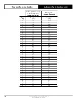
Страница 13: ...e Ω Orange Grey 46 3 Ω Red Grey 46 3 Ω Yellow Grey 46 3 Ω Black Grey 46 3 Ω Resistance value at 20o C Ambient Temperature 04 09 Temperature Resistance Table For Sensors Ambient Outdoor Coil Indoor Coil Suction Temperature Sensor Discharge Line Temperature Sensor Temp C Resistance KΩ Resistance KΩ 20 77 5 1053 9 19 73 5 992 1 18 69 7 933 0 17 66 1 878 0 16 62 8 827 0 15 59 6 779 6 14 56 6 734 7 13 ...

Страница 14: ...0 28 7 336 4 1 27 4 319 0 2 26 2 302 7 3 25 0 287 3 4 23 9 273 0 5 22 9 259 2 6 21 9 246 4 7 21 0 234 3 8 20 1 222 8 9 19 2 212 0 10 18 4 201 8 11 17 6 192 1 12 16 9 183 0 13 16 2 174 3 14 15 5 166 1 15 14 9 158 4 16 14 3 151 1 17 13 7 144 1 18 13 2 137 5 19 12 7 131 3 20 12 2 125 4 21 11 7 119 7 22 11 2 114 4 23 10 8 109 4 24 10 4 104 6 25 10 0 100 0 26 9 6 95 7 27 9 3 91 6 28 8 9 87 6 29 8 6 83 ...

Страница 15: ... 4 59 9 38 6 2 57 5 39 6 0 55 2 40 5 8 53 0 41 5 6 50 9 42 5 4 48 9 43 5 2 47 0 44 5 0 45 2 45 4 8 43 5 46 4 7 41 8 47 4 5 40 2 48 4 4 38 7 49 4 2 37 3 50 4 1 35 9 51 4 0 34 6 52 3 8 33 3 53 3 7 32 1 54 3 6 30 9 55 3 5 29 8 56 3 4 28 7 57 3 3 27 7 58 3 2 26 7 59 3 1 25 8 60 3 0 24 9 61 2 9 24 0 62 2 8 23 2 63 2 7 22 4 64 2 6 21 6 65 2 6 20 9 66 2 5 20 2 67 2 4 19 5 68 2 3 18 8 69 2 3 18 2 70 2 2 1...

Страница 16: ...0 78 1 8 13 5 79 1 7 13 1 80 1 7 12 7 81 1 6 12 3 82 1 6 11 9 83 1 5 11 6 84 1 5 11 2 85 1 5 10 9 86 1 4 10 5 87 1 4 10 2 88 1 3 9 9 89 1 3 9 6 90 1 3 9 3 91 1 2 9 1 92 1 2 8 8 93 1 2 8 5 94 1 1 8 3 95 1 1 8 1 96 1 1 7 8 97 1 1 7 6 98 1 0 7 4 99 1 0 7 2 100 1 0 7 0 101 1 0 6 8 102 0 9 6 6 103 0 9 6 4 104 0 9 6 2 105 0 9 6 1 106 0 9 5 9 107 0 8 5 7 108 0 8 5 6 109 0 8 5 4 110 0 8 5 3 111 0 8 5 2 11...

Страница 17: ...ng Mode Defrost Defrost Status dEF3 Status 3 min to Defrost Defrost Status dEF2 Status 2 min to Defrost Defrost Status dEF1 Status 1 min to Defrost HEAT HEAt Status Heating Mode Indoor coil pre heat after defrost oiLr Status Oil Return Operation Energy Saving dr 1 Status Demand Response Management 1 Energy Saving dr 2 Status Demand Response Management 2 Energy Saving dr 3 Status Demand Response Ma...

Страница 18: ...pen short circuit E22 E22 E22 ODU Ambient Temp Sensor Error Open short circuit E26 E26 E26 VSD VSD Supply Over Current E27 E27 E27 VSD VSD Supply Over Voltage E28 E28 E28 VSD VSD Temperature High E29 E29 E29 VSD VSD Low Supply Voltage E30 E30 E30 VSD VSD Trip Lock E41 E41 E41 VSD VSD DC Link Voltage Low E42 E42 E42 ODU Envelope Protection Error Extreme Low Evaporating Pressure E43 E43 E43 ODU Enve...

Страница 19: ... Fold Back Timeout E77 E77 E77 VSD VSD AC Input Current Fold Back Timeout E78 E78 E78 VSD VSD PFC IGBT Temp Low E79 E79 E79 VSD VSD IPM Desat Protection Compressor HW Over Current E80 E80 E80 VSD VSD Motor Temp High E81 E81 E81 VSD VSD Board Temp High E82 E82 E82 VSD VSD Power Module Temp High E83 E83 E83 VSD VSD PFC IGBT Temp High E84 E84 E84 VSD Communication Error in VSD Between DSP to PFC E85 ...

Страница 20: ...50 2 6 2875 2 8 1150 2 8 3125 3 1250 3 3375 3 2 1350 3 2 3625 3 4 1450 3 4 3875 3 6 1550 3 6 NEO Wall Controller LR7 1 LC7 2 Wall Controller Outdoor Unit CPU Category Source Function Fault E98 E98 E98 VSD VSD PFC Input Current Sensor Fault E99 E99 E99 VSD VSD Compressor Overload E100 E100 E100 VSD VSD PFC Hardware Over Current E101 E101 E101 VSD VSD PFC Software Over Current E102 E102 E102 VSD VSD...

Страница 21: ...n or short circuit Replace indoor sensor After de ice indoor fan will start after 30 seconds E04 will be displayed every time it is switched on E06 High Discharge Temperature The compressor discharge temperature Cdt has exceeded 138 C and the system has been stopped When the temperature has normalised to 80 C or 8 minutes delay has been finished the controller will attempt to return to normal cond...

Страница 22: ...pressor and fans if a pressure greater than 4502kPa is detected Compressor stops for 5 minutes for the 1st and 2nd trip If the high pressure switch trips out three times in a row then the unit will remain off for 15 minutes before attempting to re start For the system to restart after a High Pressure cut out the pressure switch needs to detect a pressure less than 3509kPa Insufficient airflow over...

Страница 23: ...oltage should be rated value range Check if the compressor is operating within specified pressure limits Find the root cause for not operating the compressor in the specified limits E28 VSD Temperature High The drive has encountered an over temperature condition and has stopped operation Verify proper airflow over the heat sink of the drive Remove any obstructions Check if the compressor is operat...

Страница 24: ...elope protection error code E42 Unit will trip on this error code if compressor is running outside the envelope boundary on extremely low evaporating pressure side for 20sec Same as E09 Same as E09 E43 Unit will trip on this error code if compressor is running outside the envelope boundary on high compression ratio side for 3sec Insufficient airflow over indoor coil during heating operation Check ...

Страница 25: ...oard Ensure correct control mode is set E56 No Master Wall Control Detected No Master Wall Control C 1 is detected System will lock out until a C 1 assignment is detected Master Controller C 1 Faulty If an additional Wall Control C 2 or C 3 is available remove the faulty Master controller and re assign one of the available controllers to C 1 Connected controller s have not been assigned as C 1 Re ...

Страница 26: ... in the specified limits Check the mounting screws on the drive If the problem still persists replace the drive Make sure they are tight E78 VSD Auto Config Communication Timeout Auto Config Communication Fault Timeout Baud rate or Parity of the system controller not matching with drive Drive is not configured Replace the drive E82 VSD Power Module Temp High Power Module Temp High Verify proper ai...

Страница 27: ...e E90 VSD Compressor Model Configuration Error Compressor Model Configuration Error Drive configuration issue Replace the drive E95 VSD Power Module Temp Low or Sensor Open or short circuit Power Module Temp Low or Sensor Open fault Verify proper airflow over the heat sink of the drive Remove any obstructions Check if the compressor is operating within specified pressure limits Find the root cause...

Страница 28: ...d Trade Marks of Actron Engineering Pty Limited ActronAir is constantly seeking ways to improve the design of its products therefore specifications are subject to change without notice Document 9590 2015 03 Ver 2 Issue Date 11 2022 Refrigerant Trading Authorisation No AU06394 ...

Отзывы: