BLACK
GREEN/
YELLOW
BROWN
BLUE
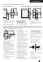
ELECTRICAL THERMAL RELEASE
(SPRING BIASED TEST SWITCH)
ELECTRICAL THERMAL RELEASE
(SPRING BIASED TEST SWITCH)
TF 72
°
C
TF 72
°
C
2
1
S2
S3
S4
S5
S6
S1
N
E
M
L
VOLT FREE CONTACT
CHANGES OVER WHEN
DAMPER RELEASED
RATED 24V 3A
VOLT FREE CONTACT
CHANGES OVER WHEN
DAMPER RESET
RATED 24V 3A
SUPPLY
24V A.C. OR D.C.
TYPICALLY 7W (MOTORING) 2W (RESET)
COMMON
NORMALLY CLOSED
NORMALLY OPEN
NORMALLY CLOSED
NORMALLY OPEN
COMMON
VOLT FREE CONTACT
CHANGES OVER WHEN
DAMPER RESET
RATED 240V 2A
COMMON
NORMALLY CLOSED
NORMALLY OPEN
2
1
S2
S3
S4
S5
S6
S1
N
M
L
VOLT FREE CONTACT
CHANGES OVER WHEN
DAMPER RELEASED
RATED 240V 3A
VOLT FREE CONTACT
CHANGES OVER WHEN
DAMPER RESET
RATED 240V 3A
SUPPLY
220 - 240V A.C. 50/60Hz
TYPICALLY 8W (MOTORING) 3W (RESET)
COMMON
NORMALLY CLOSED
NORMALLY OPEN
NORMALLY CLOSED
NORMALLY OPEN
COMMON
5
Smoke/Shield PTC™ Vent/Shield PTC™
Smoke/Shield PTC
Application and
Wiring
Mode 1
(Manual System)
Manual opening.
Spring instant closure via mechanical
fusible link.
(Smoke/Shield version only, Vent/Shield not available.)
Mode 5
(24V System)
Power On – Damper motors open.
Power Off – Spring closure or via
Electrical Thermal Release.
External mechanical position indicator
with pointer.
Release Time
≈
16 secs.
Reset Time
≈
140 secs.
(Connect 24V via a safety isolating transformer.)
Vent/Shield PTC™ dampers and
associated control modes 5 and 6
are reverse acting with spring action
opening.
Mode 6
(230V System)
Power On – Damper motors open.
Power Off – Spring closure or via
Electrical Thermal Release.
External mechanical position indicator
with pointer.
Release Time
≈
16 secs.
Reset Time
≈
1c secs.
(To isolate from main power supply, the system must
incorporate a device which disconnects the phase
conductors, with a least 3mm contact gap.)
General
One metre of halogen free low smoke
and fume electric cable is also
included with each control mode for
convenience of on site wiring. This
also provides the distinct safety
advantage of all electrics terminating
outside the duct, eliminating potential
in-duct fire hazards from wiring faults.
The Electrical Thermal Release is pre-
wired with 0.5m halogen free low
smoke and fume cabling to Control
Modes 5 and 6.
A Manual test switch fitted on the
ETR allows periodic operation of
damper simulating actual fail-safe
release under smoke/fire conditions.
Smoke/Shield and Vent/Shield
PTC™ Dampers and associated
Control Modes 5 and 6 are
available without the ETR where
thermal operation is not required.
If integrating this unit with an Actionpac
damper control system (LNS or EM)
please refer to the relevant catalogue
and specific project details.
For non ETR applications refer to
specific product label on Mode, prior
to electrical connections.


