background image

3

Smoke/Shield PTC™

Mode 1 Installation Procedure

315 

±

 20mm

40 

±


*

75mm

5mm

130mm

135mm

108

130mm

TOP

*This dimension will vary on circular damper. Select
dimension to give smoothest radius on bowden cable.

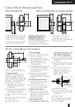
1. Prepare ductwork

Prepare ductwork for Mechanical
fusible link as detailed below. (For
ductless installations, a suitable sized
plate or bracket must be fitted to the
installation, to allow the fusible link
fixing details to be achieved).

Within the Mode 1 kit of parts, is a
self adhesive fusible link drilling
template label.

This template should be positioned
on the duct in accordance with
the dimensions shown above.

Using a 3.0mm dia bit, drill 2 fixing
holes.

Using a 25mm dia hole cutter, drill
the central hole.

Remove sharp edges.

248

28

56

84

260

100

112

12

108

70

25

130

108

130

Smoke/Shield PTC™ Control Modes
are located outside of the ductwork
for ease of access and installation.

Control Modes 5 and 6 can be fitted
in any one of three orientations i.e.

Vertically down (Position 1)
Horizontally (Position 2), or 
Vertically up (Position 3).

This can be simply and easily carried
out on site, by repositioning the
Location Plate and Control Mode on

to the 

snap

lock™ Drive Interface.

This flexibility ensures that the
damper and control mode require the
minimal amount of room.

Mode 1 (Smoke/Shield only)

Modes 5 and 6 Three position 180° (Pivotable Control Mode)

Control Mode Dimensional Data

2. Fit Control Mode

Remove transit plate from damper
shroud, and discard.

Slide the interface and mode
assembly into the shroud, having
ensured that the slots in the
interface case and the drive
coupling are in line.

Push the assembly fully home until
the spring retaining pin engages
through the location hole in the
shroud (

snap

lock™ ).

(The mode 1 option, unlike the
mode 5/6, does not have the
facility of alternative actuator fixing
positions).

3. Fit Mechanical Fusible Link

Locate the fusible link assembly in
the prepared hole in duct.

Using the 2 self tapping screws
provided, secure the assembly.

4. Electrical Connections

Where use is to be made of the
integral microswitch for indication
purposes, this should be wired as
described in the section
‘Application and wiring’.

5. Reset and Test Unit

If the mechanical fusible link is

not fitted to the ductwork, it will
not be possible to reset the
unit. – This is a safety feature.

Using a 14mm A/F spanner, rotate
the input shaft clockwise to reset
the damper.

NOTE: After resetting, never leave
the spanner attached to the reset
shaft.

Test unit by simply unscrewing
wing nut of the fusible link
assembly. This will result in the
damper releasing. Check for
damper closure.

FUSIBLE LINK

Re-tighten the wing nut.

Using a 14mm A/F spanner, rotate
the input shaft clockwise to reset
the damper.

Remove spanner.

Note: It will not be possible to reset
the control mode if the fusible link is
not correctly installed.

Содержание Smoke/Shield PTC

Страница 1: ...lication and Wiring 5 Hot Shield PTC and Hot Shield Vent PTC Damper Installation and Dimensional Data Application and Wiring 6 Hot Shield PTC and Hot Shield Vent PTC Dimensional Data 7 Hot Shield PTC and Hot Shield Vent PTC Multiple Assembles 7 Smoke Shield PTC Vent Shield PTC Hot Shield PTC and Hot Shield Vent PTC Troubleshooting 8 Smoke Shield PTC Modes 1 5 6 fail safe spring close with manual o...

Страница 2: ...tallation frames are delivered to site as a complete assembly with the appropriate PTC damper fitted therein The damper shall be installed centrally in the thickness of a brickwork or concrete surrounding wall or floor or in the case of thick walls or floors so that the centre line of the frame is at least 50mm but not more than 75mm away from the nearest face of the wall or floor in which the ass...

Страница 3: ... Three position 180 Pivotable Control Mode Control Mode Dimensional Data 2 Fit Control Mode Remove transit plate from damper shroud and discard Slide the interface and mode assembly into the shroud having ensured that the slots in the interface case and the drive coupling are in line Push the assembly fully home until the spring retaining pin engages through the location hole in the shroud snaploc...

Страница 4: ...ess installations the ETR should be fitted onto the damper spigot not casing above the damper shroud and in accordance with these fitting instructions The damper should be manually reset and released using the winder provided to ensure that correct mechanical operation is achievable It is possible to mechanically lock open the Smoke Shield PTC damper to allow air to pass through it by using the wi...

Страница 5: ...s Connect 24V via a safety isolating transformer Vent Shield PTC dampers and associated control modes 5 and 6 are reverse acting with spring action opening Mode 6 230V System Power On Damper motors open Power Off Spring closure or via Electrical Thermal Release External mechanical position indicator with pointer Release Time 16 secs Reset Time 1c secs To isolate from main power supply the system m...

Страница 6: ...urposes Please contact our Customer Service Office for details when incorporating thickened fire rated ductwork 411 421 161 27 191 Damper Installation and Control Mode Fitting Series 2501 Hot Shield PTC Application and Wiring 1 2 1 2 3 4 VOLT FREE CONTACT CLOSED WHEN DAMPER RELEASED VOLT FREE CONTACT CLOSED WHEN DAMPER RESET A C D C 24V 50 60 Hz 10 V A 7 2 W 30 50 C CONTINUOUS A C 250V 6 3 A SUPPL...

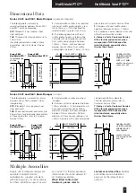
Страница 7: ...mpers with duct diameters between 100mm diameter 150mm diameter will have nominal damper size of 200mm diameter Dampers with duct diameters between 151mm diameter 982mm diameter will have nominal damper size 50mm Dampers with a nominal damper size between 983mm diameter 1000mm diameter please refer to Customer Service Office 7 Always refer to Customer Service Office for dimensional data when incor...

Страница 8: ...rrectly wired The ETL cables have been damaged or tampered with Control Mode operates but limited or no movement of damper blades is observed The mode is not correctly synchronised with the interface The damper is damaged or poorly installed The retaining pin in the interface is not protruding through the location hole in the shroud Foreign matter is impeding blade movement Location plate omitted ...

Отзывы: