GENERAL -
READ COMPLETELY BEFORE INSTALLING
This product allows for several optional installation
methods. Available methods for walls are shown here. The
raceway (device) consists of an enclosed heavy gauge
galvanized steel channel with a detachable lid. Depending
on the type ordered, wall plates and gaskets are either
included or may be ordered separately. Wall plates are
designed to accommodate single, double, or triple device
installations. Component requirements will vary according to
the method of installation chosen. See Table B for
additional information.
NOTE: WALL INSTALLATIONS REQUIRE THIS DEVICE TO BE INSTALLED WITH
THE TOP (LID) FACING UPWARD. The lid may be identified by the BARRIER
GAUGE stamping. WALL PLATES ARE ASYMMETRICAL and are marked with the
word TOP.
CREATING THE OPENING
Gypsum Board Walls (Square Openings):
1.
Locate suitable area of the wall to penetrate making sure that there are no studs, wires, pipes or other obstructions
located within wall.
2.
Mark a square or rectangular opening as dimensioned in Table A. Make sure opening is square and plumb. The
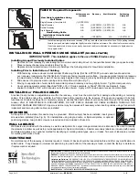
inside opening of the wall plates can be used as a template (See Fig. 1).
3.
Using a keyhole saw, cut wall board (See Fig. 2). Cutting to the outside of the line will produce a slightly over-sized
opening. Mark and cut opposite side of the wall, exercising care to align both openings. Insert raceway and check
for fit. Remove raceway.
4.
Install device per instructions below.
Concrete or Masonry Walls (Square or Round Openings):
1.
Cut or form a square or rectangular opening or core drill a round opening per dimensions listed in Table A.
INSTALLING WIREWAY USING WALL PLATES
Prior to Pulling Cables
Device is installed through wall and attached using wall plates to sandwich the wall. No mechanical attachment to wall
itself is required.
1.
Pre-install required set screws in wall plates using allen wrench (provided).
NOTE: When installing a single wall plate and raceway, two set screws positioned and tightened at 90 degrees to each other in both plates will adequately hold device (See
Fig. 4). Multiple devices in a ganged installation using double (Cat No. EZP233W) or triple wall plates (EZP333W) require EVERY set screw to be installed.
2.
Install a wall plate around raceway making sure that set screw flanges are facing towards the end of the device.
NOTE: Position plate so that the word TOP stamped on the plate aligns with the lid of the raceway. Use gauge marks located on lid of raceway to adjust plate to thickness
of wall (See Fig. 3). This will center raceway within the wall. When properly adjusted, tighten set screws to lock plate onto raceway.
3.
Place one of two provided foam gaskets around opposite end of raceway and carefully slide it back to fit snugly
against back side (wall side) of plate.
4.
Insert raceway through wall (with TOP facing upwards) using previously installed wall plate and gasket as a stop
(See Fig. 5).
5.
Moving to the opposite side of the wall, install remaining foam gasket around raceway and slide toward wall.
Page 1 of 2
Installation Sheet •
EZ PATH
ZIS1003
01/03
INSTALLATION SHEET
EZ PATH™ Fire Rated Pathway
Fig. 1
Fig. 3
TABLE A: Wall Opening Dimensions
CONFIGURATION
SINGLE
DOUBLE
TRIPLE
Square or Rectangular Using Wall Plates - Gypsum Board or Masonry
Opening Height
3 1/8”
3 1/8”
3 1/8”
Opening Width
3 1/8”
6 1/8”
9 1/8”
Square (Using Sealant - No Wall Plates) - Gypsum Board or Masonry
Opening Height
3 1/8”
N/A
N/A
Opening Width
3 1/8”
N/A
N/A
Round (Using Sealant - No Wall Plates) - Masonry
Opening Diameter
4”
N/A
N/A
Fig. 2
°
Fig. 4
Fig. 5
CITY OF NEW YORK MEA 369-02-M


