background image

Suburban Dynaline 3 A&E Manual 12/2021 Rev.2

29

Built-in Thermostat Control – Heat Mode

Initial Lighting Instructions


1. Open the manual shut-off valve. The valve is fully open when the 

  handle is level or parallel to the gas line. Never attempt to operate unit 

  with manual valve partially closed.
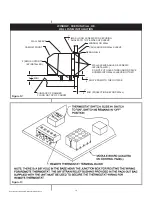
2. Depress “System” key pad until heat lamp    

  is illuminated. (See 

Figure 32

.)

3. Depress “Fan” key pad until desired speed    

  lamp is illuminated. (See 

Figure 32

.)

4. Set thermostat to desired setting by    


  depressing temperature-indicating arrows    

  until desired temperature is displayed.
5. If the thermostat circuit is closed at the  


  setting chosen in Step #4, the ignition  


  sequence begins. After approximately 

  20-25 seconds, the main burner should 

  be established.
6. After ignition, the operation of the 

  unit will be controlled automatically by 

  the thermostat.

To Shut Down for an Extended Period of Time

1. Depress “System” key pad until standby lamp is illuminated.
2. Close manual shutoff valve.

Sequence of Normal Operation – Heat Mode

1. When heat is required, the thermostat closes and energizes the combustion  

  air motor and the supply air motor.
2. As the blower reaches approximately 90% of the normal RPM, the 

  pressure created by the combustion air motor causes the diaphragm in 

  the pressure switch to move, closing the contacts. This completes the 

  electrical circuit to the input of the module board and a 10-second 

  warm-up period for the glo-bar is established. During the warm-up period,    

the glo-bar comes on for 10 seconds, then the valve opens. The glo-bar  


  remains on another 3 seconds after the valve opens and then goes off.  


  When the valve opens, it will remain open for 6 seconds. Gas will flow 

  to the burner and be ignited by the glo-bar.
3. If the main burner flame is sensed, the burner will remain on until 

  the thermostat is satisfied. If the flame is not sensed, the gas valve closes  


  and the ignition sequence is automatically repeated two (2) times. If the  


  burner does not light during this trial for ignition period, the unit will 

  lock out for one (1) hour and then re-set automatically.

NOTE:

 If lock-out should occur, the unit can be re-set manually by selecting 

Standby and then selecting Heat Mode. The ignition procedures can now  

be repeated. Should repeated lock-out occur, shut unit down and contact 

service agency.
4. When the thermostat is satisfied, the valve closes. The combustion 

  air motor will remain on for a 30-second purge cycle, then goes off. The  


  room air blower will continue to operate for approximately 90 seconds at    

  which time the circuit is opened and the room air blower goes off.

OPERATING INSTRUCTIONS 

DIGITAL KEY PAD 

CONTROL

  Figure 30

SYSTEM

SYSTEM

FFAN

AN

ST

STANDBY

ANDBY

HEA

HEATT
COOL

COOL
FFAN ONL

AN ONLYY

HIGH

HIGH
LOW

LOW

SET

SET

COOLER

COOLER

W

WARMER

ARMER

SER

SERVICE SYSTEM

VICE SYSTEM

Содержание Suburban Dynaline 3 DYNA07AC

Страница 1: ...s Motels Apartments and Senior Housing Three BTU h Capacities 12 20 MBTU Gas Heat Low Heating Amp Draw R 410A Refrigerant ARCHITECT S AND ENGINEER S MANUAL A Combination Gas Heating Electric Cooling S...

Страница 2: ...o open flame is the modern alternative to pilot lights HSI increases energy conservation while ensuring safety Easy to Install and Service Gas LP or Natural connections may be inside or outside the ro...

Страница 3: ...g Tips 33 Accessory Description Review 34 Dynaline 3 Airflow 35 Suburban Limited Warranty 36 37 Dynaline 3 PTAC Features and Benefits 38 39 Hotels Motels Individual room control Energy management inte...

Страница 4: ...or each specific locale Utilizing BIN Hour temperature data the following table provides representative examples of costs to operate one PTAC for one year Suburban will gladly prepare a BIN Hour Cost...

Страница 5: ...er year at the mid point temperature specific to a geographical location The BIN hours are derived from historical weather data For example at a location with 7 023 heating BIN hours such as Syracuse...

Страница 6: ...g infiltration of air water and contaminants into the conditioned area Electrical components Located on the indoor side of the wall they are protected from the weather and easily accessed for service...

Страница 7: ...32 21 14 7 8 1 16 7 25 32 42 7 14 42 16 16 42 11 16 40 5 8 3 8 14 3 4 UNIT WALL SLEEVE DIMENSIONS Figure 4 Specifications subject to change without notice Freeze Protection Forces heating operation i...

Страница 8: ...50 1125 150 1550 260 Min Wire Size Copper 14 AWG 14 AWG 14 AWG 14 AWG 14 AWG Protection Fused 2 15 amp 2 15 amp 2 15 amp 2 15 amp 2 15 amp Protection Circuit HACR type Dual 15 amp Dual 15 amp Dual 15...

Страница 9: ...and Hi Low heat speeds and a fan cycle switch to permit continuous indoor fan operation A separate condenser fan operates in the A C cycle only The condenser fan not operating in the heating mode elim...

Страница 10: ...ructed of 20 gauge galvanized steel with a protective baked on enamel finish similar to the wall case GAS TYPE Natural gas units shall be equipped with a gas valve having a built in regulator set to o...

Страница 11: ...unit should be installed where it can effectively circulate air into the room Generally the best location is midway along the wall and away from a stairwell or other opening Unit must not be located...

Страница 12: ...a location inspect the wall and floor areas to determine that there are no hidden electrical wires piping tubing ducts girders wall studs etc that might interfere with the proper installation and safe...

Страница 13: ...4 slope to the outside Do not slope toward front To avoid water damage to the wall do not put holes through the bottom of the wall sleeve NOTE If the unit is to be mounted flush with the exterior wall...

Страница 14: ...Remote thermostat Dynaline 3 chassis are supplied for standard built in control To convert the standard chassis to function with remote thermostat connect the thermostat wiring according to thermosta...

Страница 15: ...HED INTERIOR WALL SURFACE OF FINISHED INTERIOR WALL CABINET FRONT SLOPE DOWN TO THE OUTSIDE MIN PROJECTION BEYOND EXTERIOR WALL MOUNTING HOLES AND SCREWS BY INSTALLER DO NOT PUT HOLES THROUGH WALL SLE...

Страница 16: ...LL WALL SLEEVE ANGLES SCREWS BY INSTALLER DO NOT PUT HOLES THROUGH OR DRIVE SCREWS INTO WALL SLEEVE BOTTOM CAULK AROUND WALL SLEEVE WINDOW OR WALL CABINET FRONT WALL SLEEVE MAX LONG SCREWS FOR SECURIN...

Страница 17: ...f pipe of different diameters and lengths in cubic feet per hour with pressure drop of 0 3 inches and specific gravity of 0 60 inches Iron Pipe Sizes IPS Inches Pipe Length feet 1 2 3 4 1 1 1 4 1 1 2...

Страница 18: ...15 4 Using the two 2 8 32 x 1 2 self tapping screws provided secure hi ear elbow as illustrated See C Figure 15 5 Insert gas inlet tube assembly See D Figure 15 through bushing in firewall NOTE The sh...

Страница 19: ...arge to the right but can easily be converted for discharge to the left The adaptor is 43 1 4 long with female connection The extension is 43 1 4 long with 1 male tapered flange If you wish to dischar...

Страница 20: ...diameter hole 2 places 9 Install adaptor and collar assembly on unit as illustrated and secure with the two 2 screws retained in Step 5 Also secure the adaptor to the adaptor brackets with the screws...

Страница 21: ...daptor and collar assembly from the unit At the two locations marked on the adaptor in Step 8 drill a 7 64 diameter hole 2 places 10 Install adaptor and collar assembly on unit as illustrated and secu...

Страница 22: ...rolled by a toggle switch or other means in a control panel field supplied The units remain de energized until the room becomes occupied at which time the desk attendant can energize them The standard...

Страница 23: ...les of exterior grilles are available to complement building aesthetics Aluminum Grille Unpainted grille of stamped clear anodized aluminum Protects the outdoor fan coil and vent cap assembly Designed...

Страница 24: ...as in the event of a diaphragm rupture Gas escapement is limited within ANSI standard levels Multipurpose mounting internal or external For best performance and quick response mount in upright positi...

Страница 25: ...t the chassis built in thermostat Schematic 208 230 V A C ELECTRICAL CONNECTIONS AND WIRING C S BR Y R Y COMPRESSOR MOTOR BR ROOM AIR BR BK EXHAUST MOTOR BK MOTOR BR BR 2 4 3 1 IGNITOR 10 11 12 7 8 9...

Страница 26: ...ESSOR RELAY 8 1 HI LIMIT 2 11 PRESSURE 7 4 CONDENSOR MOTOR TEMP SENSE LO HI AIR MOTOR ROOM POWER EMERGENCY 12 3 EXHAUST MOTOR 24V 230V 6 9 FLAME PROBE ROCKER SWITCH 208VAC 230VAC SW FLUE LIMIT G 24VAC...

Страница 27: ...ency power generator without forfeiting zone temperature control on the heating cycle Dynaline 3 incorporates an A C compressor lock out capability This feature allows the compressor circuit to be loc...

Страница 28: ...ust gases through the unit s vent system is obstructed creating an unsafe condition If the limit switch is determined to be defective it must be replaced Never attempt to repair it and never shunt the...

Страница 29: ...This completes the electrical circuit to the input of the module board and a 10 second warm up period for the glo bar is established During the warm up period the glo bar comes on for 10 seconds then...

Страница 30: ...temperature rise the switch will close and the compressor will again come on provided that the thermostat is still calling for cooling NOTE Dynaline 3 has a built in 5 minute delay between compressor...

Страница 31: ...rise the switch will close and the compressor will again come on provided that the thermostat is still calling for cooling NOTE Dynaline 3 has a built in 5 minute delay between compressor cycles Anyt...

Страница 32: ...tor Air Discharge Lateral Connector 43 Air Discharge Lateral Extension 43 Rear Gas Connection Kit Field Installed 2 PSIG Regulator Leveling Legs Set of 2 each Decor Base Panel conceals gas electric co...

Страница 33: ...r either horizontally or vertically The grille is installed from the factory to deliver horizontal air flow To change the airflow to vertical simply remove the grille and reinstall in the opposite pos...

Страница 34: ...or any other material charges 2 Damages caused by shipping accident abuse negligence misuse fire flood or Acts of God 3 Damages caused by operating or staging the unit in a corrosive environment 4 Dam...

Страница 35: ...n the product or with your homeowners manual If his name is not known call your builder or general contractor if yours is a new structure SECOND Contact the Suburban distributor who supplied the produ...

Страница 36: ...case they prevent the infiltration of air water and contaminants intothe conditioned area Air Vent The manually operated lever allows entry of 70 CFM of outside air into the comfort area Return Air Fi...

Страница 37: ...ncrease in temperature than an all electric unit Economical Gas Heat Provides Comfort to Those Who Need it the Most The Dynaline 3 Difference Dynaline 3 provides warm gas heat In cooler climates parti...

Страница 38: ...request A complete warranty statement can be found in each product s Installation Operation Manual on our website As part of the Suburban continuous improvement program specifications are subject to...

Отзывы: