Suburban Dynaline 3 A&E Manual 12/2021 Rev.2
18
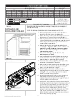
INSTALLING REAR
GAS CONNECTION
WITH REAR GAS
HOOK-UP KIT
Dynaline
™
3 chassis are manufactured for front gas hook-up. The optional
rear gas hook-up kit can be used for field conversion of the chassis to a rear
gas hook-up at the RH side (facing back of the unit).
1. Remove cabinet front.
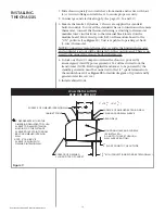
2. Remove brass street elbow from valve and replace it with the 3/8" NPT
x 3/8" flare elbow provided. Be sure to apply a thread compound
resistant to the action of liquefied petroleum (LP) gas and Natural gas
to the threads. NOTE: Flared portion of elbow must be pointing up.
Do not discard the elbow that was removed. It will be used later.
(See
A, Figure 15
.)
3. Remove the 1-1/8" plug from the firewall and replace it with the 1-1/8"
universal bushing provided. (See
B, Figure 15
.)
4. Using the two (2) 8-32 x 1/2 self tapping screws provided, secure hi-ear
elbow as illustrated. (See
C, Figure 15
.)
5. Insert gas inlet tube assembly. (See
D, Figure 15
) through bushing in
firewall. NOTE: The shortest end of the tube connects to main gas valve.
6. Secure tube assembly to elbows as illustrated. (See
Figure 15
.) Do not
apply thread compound to flare fittings.
7. Using silicone caulking, seal gas inlet tube assembly where it passes
through bushing. (See
E, Figure 15
.)
8. Install street elbow removed from valve in Step #2. Clean threads, and
apply new thread compound sealant. Secure street elbow to the 90°
hi-ear elbow that was attached to chassis in Step #4. Female threads
must be pointing down.
9. Install chassis into wall sleeve.
10. Chassis installation into wall case can now be completed by installing
nipple, union and shutoff valve (field supplied) in accordance with
local code.
11. Check all joints for gas leaks.
NOTE: Wall sleeve must extend beyond the finished exterior wall surface
1-5/8" minimum.


