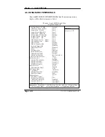


Chapter 4 Award BIOS Setup
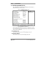
Please be aware that if select the wrong panel type, it may cause the
abnormal display of the LCD.
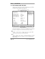
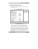
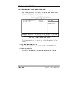
DRAM TIMING BY SELECTABLE:
This allows you to select the DRAM timing.
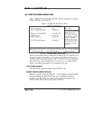
CAS LATENCY TIME:
When synchronous DRAM is installed, the number of clock cycles of CAS
latency depends on the DRAM timing.
ACTIVE TO PRECHARGE DELAY:
This item controls the number of DRAM clocks for TRAS.
DRAM RAS# TO CAS# DELAY:
This field let’s you insert a timing delay between the CAS and RAS strobe
signals, used when DRAM is written to, read from, or refreshed. Fast gives
faster performance; and Slow gives more stable performance. This field
applies only when synchronous DRAM is installed in the system.
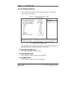
DRAM RAS# PRECHARGE:
If an insufficient number of cycles is allowed for the RAS to accumulate its
charge before DRAM refresh, the refresh may be incomplete and the DRAM
may fail to retain data. Fast gives faster performance; and Slow gives more
stable performance. This field applies only when synchronous DRAM is
installed in the system.
SYSTEM BIOS CACHEABLE:
Selecting Enabled allows caching of the system BIOS ROM at F0000h-
FFFFFh, resulting in better system performance. However, if any program
writes to this memory area, a system error may result.
VIDEO BIOS CACHEABLE:
Select Enabled allows caching of the video BIOS, resulting in better system
performance. However, if any program writes to this memory area, a system
error may result.
MEMORY HOLE AT 15M-16M:
You can reserve this area of system memory for ISA adapter ROM. When
this area is reserved, it cannot be cached. The user information of
Page: 4-12
PC 5171 USER
c
S MANUAL
Содержание PC 5171
Страница 1: ...USER S MANUAL PC 5171 Socket 478 P4 P4 M 17 inch Panel PC System...
Страница 9: ...Chapter 1 Introduction 1 2 CASE ILLUSTRATION PC 5171 USERc MANUAL Page 1 3...
Страница 21: ...Chapter 2 Hardware Configuration JUMPER DIAGRAMS JUMPER SETTINGS PC 5171 USER S MANUAL Page 2 5...
Страница 25: ...Chapter 2 Hardware Configuration RI 15 16 COM2 Max 1A 5V 4 6 12V 2 4 PC 5171 USER S MANUAL Page 2 9...
Страница 26: ...Chapter 2 Hardware Configuration RI 17 18 COM3 Max 1A 5V 7 9 12V 9 11 Page 2 10 PC 5171 USER S MANUAL...
Страница 27: ...Chapter 2 Hardware Configuration RI 19 20 COM4 Max 1A 5V 8 10 12V 10 12 PC 5171 USER S MANUAL Page 2 11...
Страница 92: ...Appendix A System Assembly EXPLODED DIAGRAM FOR REMOVING HOOK HOLDER PC 5171 USERcS MANUAL Page A 3...
Страница 93: ...Appendix A System Assembly EXPLODED DIAGRAM FOR REMOVING EXT CASE Page A 4 PC 5171 USERcS MANUAL...
Страница 94: ...Appendix A System Assembly EXPLODED DIAGRAM FOR REMOVING BACK COVER PC 5171 USERcS MANUAL Page A 5...
Страница 95: ...Appendix A System Assembly EXPLODED DIAGRAM FOR REMOVING LCD ASSEMBLY Diagram 1 Page A 6 PC 5171 USERcS MANUAL...
Страница 96: ...Appendix A System Assembly Diagram 2 PC 5171 USERcS MANUAL Page A 7...
Страница 97: ...Appendix A System Assembly EXPLODED DIAGRAM FOR FRONT PANEL Diagram 1 Page A 8 PC 5171 USERcS MANUAL...
Страница 98: ...Appendix A System Assembly Diagram 2 PC 5171 USERcS MANUAL Page A 9...
Страница 99: ...Appendix A System Assembly EXPLODED DIAGRAM FOR REMOVING CD ROM ASSEMBLY Page A 10 PC 5171 USERcS MANUAL...
Страница 100: ...Appendix A System Assembly EXPLODED DIAGRAM FOR REMOVING HDD ASSEMBLY PC 5171 USERcS MANUAL Page A 11...
Страница 101: ...Appendix A System Assembly EXPLODED DIAGRAM FOR REMOVING MOTHERBOARD AND POWER Page A 12 PC 5171 USERcS MANUAL...
Страница 102: ...Appendix A System Assembly EXPLODED DIAGRAM FOR REMOVING OUTPUT PANEL PC 5171 USERcS MANUAL Page A 13...
Страница 103: ...Appendix A System Assembly EXPLODED DIAGRAM FOR REMOVING FDD CD ROM Diagram 1 Remove FDD Page A 14 PC 5171 USERcS MANUAL...
Страница 104: ...Appendix A System Assembly Diagram 2 Remove CD ROM PC 5171 USERcS MANUAL Page A 15...
Страница 105: ...Appendix A System Assembly EXPLODED DIAGRAM FOR REMOVING MASK Page A 16 PC 5171 USERcS MANUAL...
Страница 106: ...Appendix A System Assembly EXPLODED DIAGRAM FOR WALL MOUNTING Diagram 1 PC 5171 USERcS MANUAL Page A 17...
Страница 107: ...Appendix A System Assembly Diagram 2 Page A 18 PC 5171 USERcS MANUAL...
Страница 108: ...Appendix A System Assembly Diagram 3 Diagram 4 PC 5171 USERcS MANUAL Page A 19...
Страница 110: ...Appendix B Technical Summary BLOCK DIAGRAM Page B 2 PC 5171 USERcS MANUAL...


