

Chapter 4 Award BIOS Setup
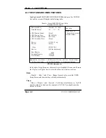
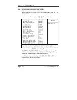
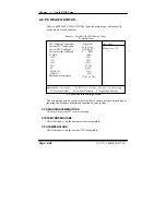
TYPEMATIC RATE SETTING:
Enable this item if you wish to be able to configure the characteristics of
your keyboard. Typematic refers to the way in which characters are entered
repeatedly if a key is held down. For example, if you press and hold down
the "A" key, the letter "a" will repeatedly appear on your screen on your
screen until you release the key. When enabled, the typematic rate and
typematic delay can be selected.
TYPEMATIC RATE (CHARS/SEC):
This item sets the number of times a second to repeat a key stroke when you
hold the key down.
TYPEMATIC DELAY (MSEC):
The item sets the delay time after the key is held down before it begins to
repeat the keystroke.
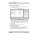
SECURITY OPTION:
This category allows you to limit access to the system and Setup, or just to
Setup.
System
The system will not boot and access to Setup will be
denied if the correct password is not entered at the
prompt.
Setup
The system will boot, but access to Setup will be
denied if the correct password is not entered at the
prompt.
To disable security, select PASSWORD SETTING at Main Menu and
then you will be asked to enter password. Do not type anything and just
press <Enter>, it will disable security. Once the security is disabled, the
system will boot and you can enter Setup freely.
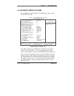
OS SELECT FOR DRAM >64MB :
Select the operating system that is running with greater than 64MB or RAM
on the system. You may choose OS2 or Non-OS2.
Page: 4-10
PC 5171 USER
c
S MANUAL
Содержание PC 5171
Страница 1: ...USER S MANUAL PC 5171 Socket 478 P4 P4 M 17 inch Panel PC System...
Страница 9: ...Chapter 1 Introduction 1 2 CASE ILLUSTRATION PC 5171 USERc MANUAL Page 1 3...
Страница 21: ...Chapter 2 Hardware Configuration JUMPER DIAGRAMS JUMPER SETTINGS PC 5171 USER S MANUAL Page 2 5...
Страница 25: ...Chapter 2 Hardware Configuration RI 15 16 COM2 Max 1A 5V 4 6 12V 2 4 PC 5171 USER S MANUAL Page 2 9...
Страница 26: ...Chapter 2 Hardware Configuration RI 17 18 COM3 Max 1A 5V 7 9 12V 9 11 Page 2 10 PC 5171 USER S MANUAL...
Страница 27: ...Chapter 2 Hardware Configuration RI 19 20 COM4 Max 1A 5V 8 10 12V 10 12 PC 5171 USER S MANUAL Page 2 11...
Страница 92: ...Appendix A System Assembly EXPLODED DIAGRAM FOR REMOVING HOOK HOLDER PC 5171 USERcS MANUAL Page A 3...
Страница 93: ...Appendix A System Assembly EXPLODED DIAGRAM FOR REMOVING EXT CASE Page A 4 PC 5171 USERcS MANUAL...
Страница 94: ...Appendix A System Assembly EXPLODED DIAGRAM FOR REMOVING BACK COVER PC 5171 USERcS MANUAL Page A 5...
Страница 95: ...Appendix A System Assembly EXPLODED DIAGRAM FOR REMOVING LCD ASSEMBLY Diagram 1 Page A 6 PC 5171 USERcS MANUAL...
Страница 96: ...Appendix A System Assembly Diagram 2 PC 5171 USERcS MANUAL Page A 7...
Страница 97: ...Appendix A System Assembly EXPLODED DIAGRAM FOR FRONT PANEL Diagram 1 Page A 8 PC 5171 USERcS MANUAL...
Страница 98: ...Appendix A System Assembly Diagram 2 PC 5171 USERcS MANUAL Page A 9...
Страница 99: ...Appendix A System Assembly EXPLODED DIAGRAM FOR REMOVING CD ROM ASSEMBLY Page A 10 PC 5171 USERcS MANUAL...
Страница 100: ...Appendix A System Assembly EXPLODED DIAGRAM FOR REMOVING HDD ASSEMBLY PC 5171 USERcS MANUAL Page A 11...
Страница 101: ...Appendix A System Assembly EXPLODED DIAGRAM FOR REMOVING MOTHERBOARD AND POWER Page A 12 PC 5171 USERcS MANUAL...
Страница 102: ...Appendix A System Assembly EXPLODED DIAGRAM FOR REMOVING OUTPUT PANEL PC 5171 USERcS MANUAL Page A 13...
Страница 103: ...Appendix A System Assembly EXPLODED DIAGRAM FOR REMOVING FDD CD ROM Diagram 1 Remove FDD Page A 14 PC 5171 USERcS MANUAL...
Страница 104: ...Appendix A System Assembly Diagram 2 Remove CD ROM PC 5171 USERcS MANUAL Page A 15...
Страница 105: ...Appendix A System Assembly EXPLODED DIAGRAM FOR REMOVING MASK Page A 16 PC 5171 USERcS MANUAL...
Страница 106: ...Appendix A System Assembly EXPLODED DIAGRAM FOR WALL MOUNTING Diagram 1 PC 5171 USERcS MANUAL Page A 17...
Страница 107: ...Appendix A System Assembly Diagram 2 Page A 18 PC 5171 USERcS MANUAL...
Страница 108: ...Appendix A System Assembly Diagram 3 Diagram 4 PC 5171 USERcS MANUAL Page A 19...
Страница 110: ...Appendix B Technical Summary BLOCK DIAGRAM Page B 2 PC 5171 USERcS MANUAL...


