
Chapter 4 Award BIOS Setup
ƒ
LBA (Logical Block Addressing): During drive accesses, the IDE
controller transforms the data address described by sector, head
and cylinder number into a physical block address, significantly
improving data transfer rates. For drives greater than 1024
cylinders.
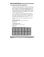
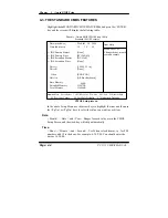
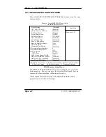
DRIVE A AND DRIVE B:
Select the type of floppy disk drive installed in your system. The available
options are 360KB 5.25in, 1.2KB 5.25in, 720KB 3.5in, 1.44MB 3.5in,
2.88MB 3.5in and None.
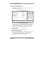
VIDEO:
This category selects the type of video adapter used for the primary system
monitor. Although secondary monitors are supported, you do not have to
select the type in Setup. Available Options are as follows:
EGA/VGA
Enhanced Graphics Adapter/Video Graphics Array.
For EGA, VGA, SEGA, SVGA or PGA monitor
adapters.
CGA 40
Color Graphics Adapter, power up in 40 column mode.
CGA 80
Color Graphics Adapter, power up in 80 column mode.
MONO
Monochrome adapter, includes high resolution
monochrome adapters.
HALT ON:
This category allows user to choose whether the computer will stop if an error
is detected during power up. Available options are “All errors”, “No errors”,
“All, But keyboard”, “All, But Diskette”, and “All But Disk/Key”.
BASE MEMORY:
Displays the amount of conventional memory detected during boot up.
EXTENDED MEMORY:
Displays the amount of extended memory detected during boot up.
TOTAL MEMORY:
Displays the total memory available in the system.
Page: 4-6
PC 5171 USER
c
S MANUAL
Содержание PC 5171
Страница 1: ...USER S MANUAL PC 5171 Socket 478 P4 P4 M 17 inch Panel PC System...
Страница 9: ...Chapter 1 Introduction 1 2 CASE ILLUSTRATION PC 5171 USERc MANUAL Page 1 3...
Страница 21: ...Chapter 2 Hardware Configuration JUMPER DIAGRAMS JUMPER SETTINGS PC 5171 USER S MANUAL Page 2 5...
Страница 25: ...Chapter 2 Hardware Configuration RI 15 16 COM2 Max 1A 5V 4 6 12V 2 4 PC 5171 USER S MANUAL Page 2 9...
Страница 26: ...Chapter 2 Hardware Configuration RI 17 18 COM3 Max 1A 5V 7 9 12V 9 11 Page 2 10 PC 5171 USER S MANUAL...
Страница 27: ...Chapter 2 Hardware Configuration RI 19 20 COM4 Max 1A 5V 8 10 12V 10 12 PC 5171 USER S MANUAL Page 2 11...
Страница 92: ...Appendix A System Assembly EXPLODED DIAGRAM FOR REMOVING HOOK HOLDER PC 5171 USERcS MANUAL Page A 3...
Страница 93: ...Appendix A System Assembly EXPLODED DIAGRAM FOR REMOVING EXT CASE Page A 4 PC 5171 USERcS MANUAL...
Страница 94: ...Appendix A System Assembly EXPLODED DIAGRAM FOR REMOVING BACK COVER PC 5171 USERcS MANUAL Page A 5...
Страница 95: ...Appendix A System Assembly EXPLODED DIAGRAM FOR REMOVING LCD ASSEMBLY Diagram 1 Page A 6 PC 5171 USERcS MANUAL...
Страница 96: ...Appendix A System Assembly Diagram 2 PC 5171 USERcS MANUAL Page A 7...
Страница 97: ...Appendix A System Assembly EXPLODED DIAGRAM FOR FRONT PANEL Diagram 1 Page A 8 PC 5171 USERcS MANUAL...
Страница 98: ...Appendix A System Assembly Diagram 2 PC 5171 USERcS MANUAL Page A 9...
Страница 99: ...Appendix A System Assembly EXPLODED DIAGRAM FOR REMOVING CD ROM ASSEMBLY Page A 10 PC 5171 USERcS MANUAL...
Страница 100: ...Appendix A System Assembly EXPLODED DIAGRAM FOR REMOVING HDD ASSEMBLY PC 5171 USERcS MANUAL Page A 11...
Страница 101: ...Appendix A System Assembly EXPLODED DIAGRAM FOR REMOVING MOTHERBOARD AND POWER Page A 12 PC 5171 USERcS MANUAL...
Страница 102: ...Appendix A System Assembly EXPLODED DIAGRAM FOR REMOVING OUTPUT PANEL PC 5171 USERcS MANUAL Page A 13...
Страница 103: ...Appendix A System Assembly EXPLODED DIAGRAM FOR REMOVING FDD CD ROM Diagram 1 Remove FDD Page A 14 PC 5171 USERcS MANUAL...
Страница 104: ...Appendix A System Assembly Diagram 2 Remove CD ROM PC 5171 USERcS MANUAL Page A 15...
Страница 105: ...Appendix A System Assembly EXPLODED DIAGRAM FOR REMOVING MASK Page A 16 PC 5171 USERcS MANUAL...
Страница 106: ...Appendix A System Assembly EXPLODED DIAGRAM FOR WALL MOUNTING Diagram 1 PC 5171 USERcS MANUAL Page A 17...
Страница 107: ...Appendix A System Assembly Diagram 2 Page A 18 PC 5171 USERcS MANUAL...
Страница 108: ...Appendix A System Assembly Diagram 3 Diagram 4 PC 5171 USERcS MANUAL Page A 19...
Страница 110: ...Appendix B Technical Summary BLOCK DIAGRAM Page B 2 PC 5171 USERcS MANUAL...


