Appendix B Technical Summary
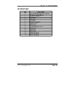
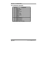
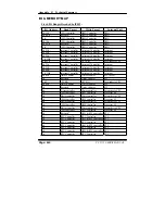
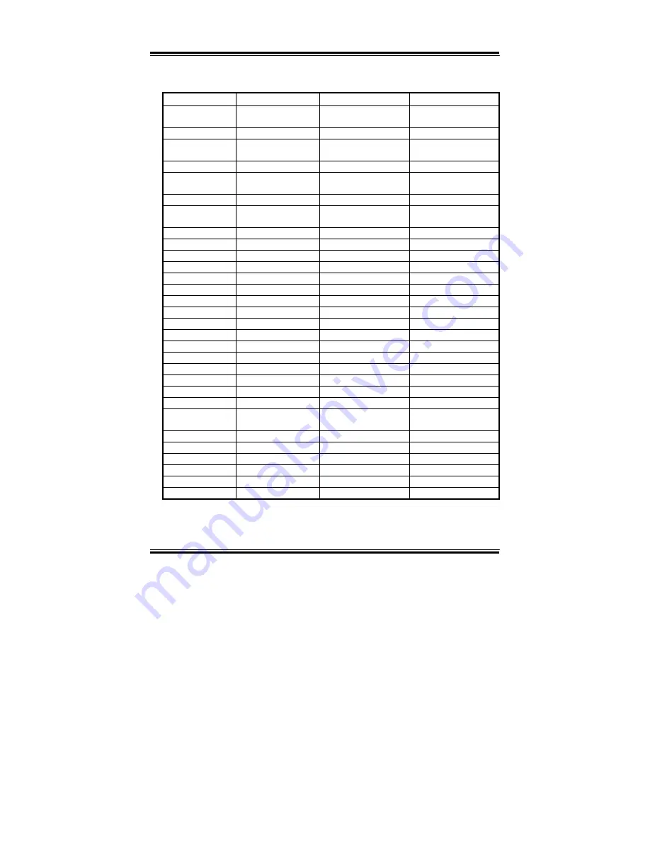
I/O Address
Read Target
Write Target
Internal Unit
80h
DMA Controller
DMA controller &
LPC/PCI
DMA
81h-83h
DMA Controller
DMA Controller
DMA
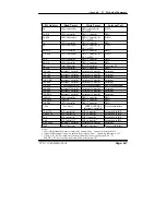
84h-86h
DMA Controller
DMA Controller &
LPC or PCI
DMA
87h
DMA Controller
DMA Controller
DMA
88h
DMA Controller
DMA Controller &
LPC or PCI
DMA
89h-8Bh
DMA Controller
DMA Controller
DMA
8Ch-8Eh
DMA Controller
DMA Controller &
LPC or PCI
DMA
08Fh
DMA Controller
DMA Controller
DMA
90h-91h
DMA Controller
DMA Controller
DMA
92h Reset
Generator
Reset
Generator Processor
I/F
93h-9Fh
DMA Controller
DMA Controller
DMA
A0h-A1h
Interrupt Controller
Interrupt Controller
Interrupt
A4h-A5h
Interrupt Controller
Interrupt Controller
Interrupt
A8h-A9h
Interrupt Controller
Interrupt Controller
Interrupt
ACh-ADh
Interrupt Controller
Interrupt Controller
Interrupt
B0h-B1h
Interrupt Controller
Interrupt Controller
Interrupt
B2h-B3h Power
Management
Power
Management Power Management
B4h-B5h
Interrupt Controller
Interrupt Controller
Interrupt
B8h-B9h
Interrupt Controller
Interrupt Controller
Interrupt
BCh-BDh
Interrupt Controller
Interrupt Controller
Interrupt
C0h-D1h
DMA Controller
DMA Controller
DMA
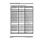
D2h-DDh Reserved
DMA Controller
DMA
DEh-DFh
DMA Controller
DMA Controller
DMA
F0h
See Note 3
FERR# /IGNNE#/
Interrupt Controller
Processor interface
170h-177h IDE Controller
1
IDE Controller
1
Forwarded to IDE
1F0h-1F7h IDE Controller
2
IDE Controller
2
Forwarded to IDE
376h IDE Controller
1
IDE Controller
1
Forwarded to IDE
3F6h IDE Controller
2
IDE Controller
2
Forwarded to IDE
4D0h-4D1h
Interrupt Controller
Interrupt Controller
Interrupt
CF9h
Reset Generator
Reset Generator
Processor interface
Notes:
1. Only if IDE Standard I/O space is enabled for Primary Drive. Otherwise, the target is PCI.
2. Only if IDE Standard I/O space is enabled for Secondary Drive. Otherwise, the target is PCI.
3. If POS_DEC_EN bit is enabled, reads from F0h will not be decoded by the ICH2. If
POS_DEC_EN is not enabled, reads from F0h will forward to LPC.
PC 5171 USER
c
S MANUAL
Page: B-7
Содержание PC 5171
Страница 1: ...USER S MANUAL PC 5171 Socket 478 P4 P4 M 17 inch Panel PC System...
Страница 9: ...Chapter 1 Introduction 1 2 CASE ILLUSTRATION PC 5171 USERc MANUAL Page 1 3...
Страница 21: ...Chapter 2 Hardware Configuration JUMPER DIAGRAMS JUMPER SETTINGS PC 5171 USER S MANUAL Page 2 5...
Страница 25: ...Chapter 2 Hardware Configuration RI 15 16 COM2 Max 1A 5V 4 6 12V 2 4 PC 5171 USER S MANUAL Page 2 9...
Страница 26: ...Chapter 2 Hardware Configuration RI 17 18 COM3 Max 1A 5V 7 9 12V 9 11 Page 2 10 PC 5171 USER S MANUAL...
Страница 27: ...Chapter 2 Hardware Configuration RI 19 20 COM4 Max 1A 5V 8 10 12V 10 12 PC 5171 USER S MANUAL Page 2 11...
Страница 92: ...Appendix A System Assembly EXPLODED DIAGRAM FOR REMOVING HOOK HOLDER PC 5171 USERcS MANUAL Page A 3...
Страница 93: ...Appendix A System Assembly EXPLODED DIAGRAM FOR REMOVING EXT CASE Page A 4 PC 5171 USERcS MANUAL...
Страница 94: ...Appendix A System Assembly EXPLODED DIAGRAM FOR REMOVING BACK COVER PC 5171 USERcS MANUAL Page A 5...
Страница 95: ...Appendix A System Assembly EXPLODED DIAGRAM FOR REMOVING LCD ASSEMBLY Diagram 1 Page A 6 PC 5171 USERcS MANUAL...
Страница 96: ...Appendix A System Assembly Diagram 2 PC 5171 USERcS MANUAL Page A 7...
Страница 97: ...Appendix A System Assembly EXPLODED DIAGRAM FOR FRONT PANEL Diagram 1 Page A 8 PC 5171 USERcS MANUAL...
Страница 98: ...Appendix A System Assembly Diagram 2 PC 5171 USERcS MANUAL Page A 9...
Страница 99: ...Appendix A System Assembly EXPLODED DIAGRAM FOR REMOVING CD ROM ASSEMBLY Page A 10 PC 5171 USERcS MANUAL...
Страница 100: ...Appendix A System Assembly EXPLODED DIAGRAM FOR REMOVING HDD ASSEMBLY PC 5171 USERcS MANUAL Page A 11...
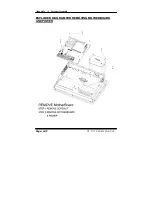
Страница 101: ...Appendix A System Assembly EXPLODED DIAGRAM FOR REMOVING MOTHERBOARD AND POWER Page A 12 PC 5171 USERcS MANUAL...
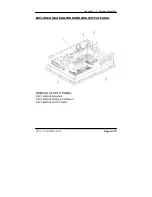
Страница 102: ...Appendix A System Assembly EXPLODED DIAGRAM FOR REMOVING OUTPUT PANEL PC 5171 USERcS MANUAL Page A 13...
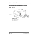
Страница 103: ...Appendix A System Assembly EXPLODED DIAGRAM FOR REMOVING FDD CD ROM Diagram 1 Remove FDD Page A 14 PC 5171 USERcS MANUAL...
Страница 104: ...Appendix A System Assembly Diagram 2 Remove CD ROM PC 5171 USERcS MANUAL Page A 15...
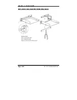
Страница 105: ...Appendix A System Assembly EXPLODED DIAGRAM FOR REMOVING MASK Page A 16 PC 5171 USERcS MANUAL...
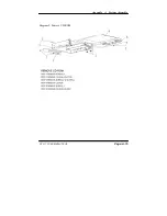
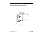
Страница 106: ...Appendix A System Assembly EXPLODED DIAGRAM FOR WALL MOUNTING Diagram 1 PC 5171 USERcS MANUAL Page A 17...
Страница 107: ...Appendix A System Assembly Diagram 2 Page A 18 PC 5171 USERcS MANUAL...
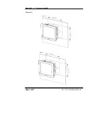
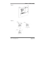
Страница 108: ...Appendix A System Assembly Diagram 3 Diagram 4 PC 5171 USERcS MANUAL Page A 19...
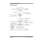
Страница 110: ...Appendix B Technical Summary BLOCK DIAGRAM Page B 2 PC 5171 USERcS MANUAL...


