


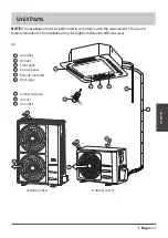
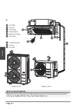


Outdoor Unit
Installation
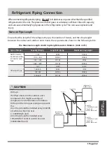
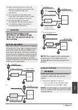
Step 2: Install drain joint(Heat pump unit only)
Before bolting the outdoor unit in place, you must
install the drain joint at the bottom of the unit.
Note that there are two different types of drain
joints depending on the type of outdoor unit.
If the drain joint comes with a rubber seal
(see
Fig. A
), do the following:
1.
Fit the rubber seal on the end of the drain joint
that will connect to the outdoor unit.
2.
Insert the drain joint into the hole in the base
pan of the unit.
3.
Rotate the drain joint 90° until it clicks in place
facing the front of the unit.
4.
Connect a drain hose extension (not included)
to the drain joint to redirect water from the
unit during heating mode.
If the drain joint doesn’t come with a rubber
seal
(see
Fig. B
), do the following:
1.
Insert the drain joint into the hole in the base
pan of the unit. The drain joint will click in
place.
2.
Connect a drain hose extension (not included)
to the drain joint to redirect water from the
unit during heating mode.
Seal
Drain joint
(A)
(B)
Base pan hole of
outdoor unit
Seal
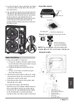
IN COLD CLIMATES
In cold climates, make sure that the drain
hose is as vertical as possible to ensure
swift water drainage. If water drains too
slowly, it can freeze in the hose and flood
the unit.
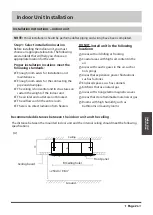
The outdoor unit can be anchored to the
ground or to a wall-mounted bracket with
bolt(M10). Prepare the installation base of
the unit according to the dimensions below.
Step 3: Anchor outdoor unit
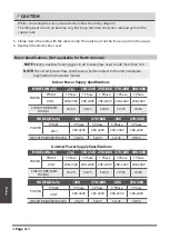
UNIT MOUNTING DIMENSIONS
The following is a list of different outdoor
unit sizes and the distance between their
mounting feet. Prepare the installation
base of the unit according to the
dimensions below.
Split Type Outdoor Unit
A
B
D
W
H
W
H
Outdoor Unit Types and Specifications
Page
34


