

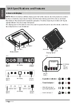
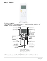


REMOTE CONTROL FUNCTIONS
Pressing the On/Off Button
When the air conditioner is not in operation, the remote
control displays the last set point and mode.
S
Press
ON/OFF
to start the unit.
−
The unit starts in the last operating mode and set point.
The
ON/OFF
indicator appears.
S
Press
ON/OFF
to stop the unit.
−
All the indicator lights on the unit go out, and the remote
control displays the set point and mode.
NOTE:
If the
ON/OFF
button is pressed too soon after a stop, the
compressor will not start for 3 to 4 minutes due to the inherent
protection against frequent compressor cycling. The unit only emits
an audible beep when the signals are received correctly.
Selecting an Operating Mode
Use the
OPERATING
mode button to select one of the available
modes.
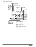
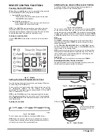
Fig. 8 − Display
Setting the Room Temperature Set Point
Press the increase temperature set point
▲
and decrease
▼
buttons
to raise or lower the temperature.
The unit confirms the signal receipt with a beep and the value of the
set temperature appears on the display and changes
accordingly. The temperature can be set between 62F (17C) and 86F
(30C) in increments of 1F or 1C.
NOTE:
In the
COOLING
mode, if the temperature selected is higher
than the room temperature, the unit will not start. The same applies
for the
HEATING
mode if the selected temperature is lower than the
room temperature.
Selecting the Fan Speed
AUTO
LOW
MED
HIGH
A14362
Fig. 9 − Fan Speeds
The fan speed can be selected by pressing the
FAN
button.
NOTE:
When the unit is on, the fan runs continuously in cooling or
heating. When in heating, there might be situations where the fan
will slow down or shut off to prevent cold blow.
Selecting the up−down airflow Louver Position
To optimize comfort, the up−down aiflow louver operates in a
preset range as shown in the following figure.
COOLING
HEATING
Fig. 10 − Louver Position
The up−down airflow louver can be adjusted by pressing
DIRECT
on the remote control and can be set to move continuously or
remain stationary by pressing
SWING
. The horizontal louver position
is stored in the settings, however it is deactivated when the
TURBO
or
MANUAL
settings are set, or when a power interruption takes
place.
Air Direction
Press
DIRECT
repeatedly to choose one of the Up−Down airflow
louver positions. Every time
DIRECT
is pushed, the specific louver
swings by 6 degrees.
In the
COOLING
,
DEHUMIDIFICATION
, and
FAN ONLY
modes,
the louver swings in the cooling range. In the
HEATING
mode, the
louver swings in the heating range.
NOTE:
Always use the remote control to adjust the up−down aiflow
louver position, otherwise abnormal operation may occur. If the up
−down airflow louver is manually adjusted out of its range, power
the unit off and then back on again.
Auto Swing
For automatic Up−Down airflow louver swing, push
SWING
.
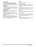
Selecting Right−Left airflow Direction of the Louver
The right-left airflow louvers can be adjusted manually to direct the
airflow to achieve optimal comfort in the space.
A07543
Fig. 11 − Right−Left Airflow Louver
Deflector rod
The louver can be taken
down by releasing the
lock block.
Fig. 12 − Louver Angles
Page
1
2


