


CAUTION
•
Ensure to wrap insulation around the piping.
Direct contact with the bare piping may
result in burns or frostbite.
•
Make sure the pipe is properly connected.
Over tightening may damage the bell mouth
and under tightening may lead to leakage.
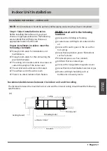
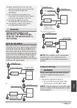
NOTE ON MINIMUM BEND RADIUS
Carefully bend the tubing in the middle
according to the diagram below.
DO NOT
bend
the tubing more than 90° or more than 3 times.
Bend the pipe with thumb
min-radius 10cm (3.9”)
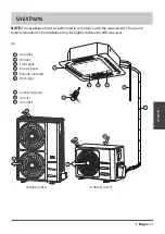
6.
After connecting the copper pipes to the
indoor unit, wrap the power cable, signal
cable and the piping together with binding
tape.
NOTE: DO NOT
intertwine signal cable with
other wires. While bundling these items
together, do not intertwine or cross the signal
cable with any other wiring.
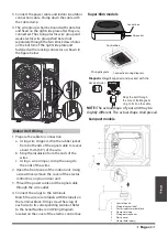
7. Thread this pipeline through the wall and
connect it to the outdoor unit.
8. Insulate all the piping, including the valves of
the outdoor unit.
9. Open the stop valves of the outdoor unit to
start the flow of the refrigerant between the
indoor and outdoor unit.
CAUTION
Check to make sure there is no refrigerant leak
after completing the installation work. If there
is a refrigerant leak, ventilate the area
immediately and evacuate the system (refer to
the Air Evacuation section of this manual).
PIPING EXTENSION BEYOND FLARE FORM
8. Remove the flaring tool and flare form,
then inspect the end of the pipe for cracks
and even flaring.
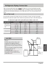
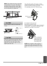
Step 4: Connect pipes
Connect the copper pipes to the indoor unit first,
then connect it to the outdoor unit. You should
first connect the low-pressure pipe, then the high-
pressure pipe.
1.
When connecting the flare nuts, apply a
thin coat of refrigeration oil to the flared
ends of the pipes.
2.
Align the center of the two pipes that you
will connect.
Indoor unit tubing
Flare nut
Pipe
3. Tighten the flare nut as tightly as possible
by hand.
4. Using a spanner, grip the nut on the unit
tubing.
5. While firmly gripping the nut, use a torque
wrench to tighten the flare nut according
to the torque values in above table.
NOTE:
Use both a spanner and a torque wrench
when connecting or disconnecting pipes to/from
the unit.
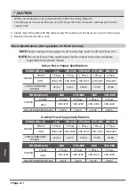
Pipe
gauge
Tightening
torque
Flare dimension (A)
(Unit: mm/Inch)
Flare shape
Min.
Max.
Ø 6.35
R0.4~0.8
45
°±
2
90
°
±
4
A
Ø 9.52
Ø 12.7
Ø 16
Ø 19
Ø 22
65-67 N.m
(663-683 kgf.cm)
23.2/0.91
23.7/0.93
75-85N.m
(765-867 kgf.cm)
26.4/1.04
26.9/1.06
18-20 N.m
(183-204 kgf.cm)
8.4/0.33
8.7/0.34
25-26 N.m
(255-265 kgf.cm)
13.2/0.52
13.5/0.53
35-36 N.m
(357-367 kgf.cm)
16.2/0.64
16.5/0.65
45-47 N.m
(459-480 kgf.cm)
19.2/0.76
19.7/0.78
Refrigerant piping
Connection
Page 3
8


