18
Chapter 2
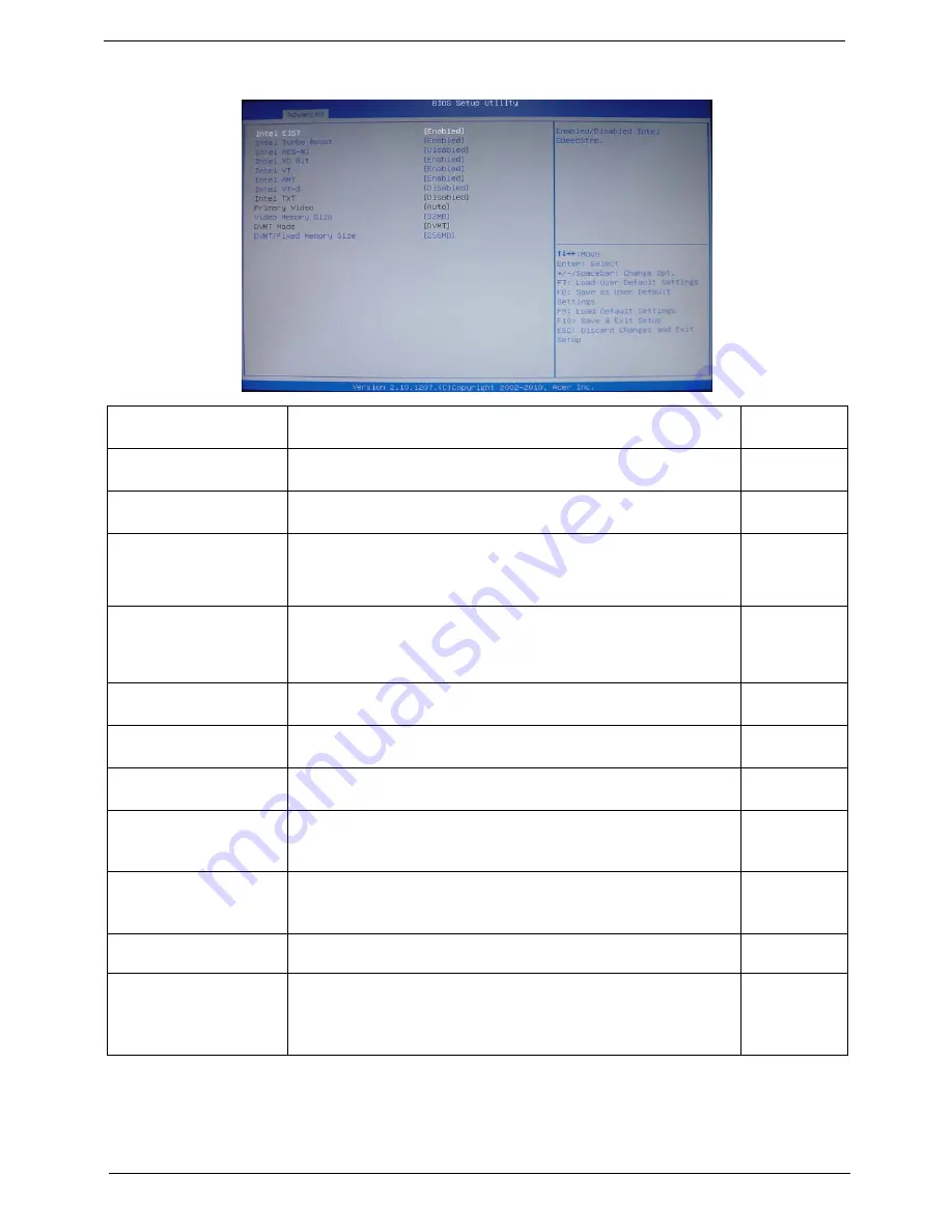
Advanced Chipset Configuration
Intel EIST
This item allows users to enable or disable the EIST (Enhanced Intel
SpeedStep technology).
Enabled
Disabled
Intel Turbo Boost
This item allows users to enable or disable the Intel Turbo Boost.
Enabled
Disabled
Intel AES-NI
Enables or disables Advanced Encryption Standard New Instructions
(AES-NI).
Enabled
Disabled
Intel XD Bit
When enabled, the processor disables code execution when a worm
attempts to insert a code in the buffer preventing damage and worm
propagation. When disabled, the processor forces the Execute Disable (XD)
Bit feature flag to always return to 0.
Enabled
Disabled
Intel VT
Enables or disables the Virtualization Technology (VT) availability. If
enabled, a virtual machine manager (VMM) can utilize the additional
hardware virtualization capabilities provided by this technology.
NOTE:
A full reset is required to change the setting.
Enabled
Disabled
Intel AMT
This item allows you to enable or disable the Intel Virtualizationa
Technology(IntelAMT) function.
Enabled
Disabled
Intel VT-d
This item allows you to enable or disable the Intel Virtualizationa
Technology(IntelVT-d) function.
Enabled
Disabled
Intel TXT
This item allows you to enable or disable the Intel Virtualizationa
Technology(IntelTXT) function.
Enabled
Disabled
Primary Video
Select a graphic controller as a primary boot device.
Auto
PCIE
Onboard VGA
Video Memory Size
This item applies to chipset/motherboards capable of the HyperMemory
Support.
32MB
64MB
128MB
DVMT Mode
DVMT is Dynamic Video Memory Technology. This item helps you select
video mode.
DVMT
DVMT/Fixed Memory Size
When set to Fixed Mode, the graphics driver will reserve a fixed portion of
the system memory as graphics memory. When set to DVMT Mode, the
graphics chip will dynamically allocate system memory as graphics memory,
according to system and graphics requirements.
128MB
256MB
Maximun
Содержание Veriton M6610
Страница 1: ...Acer Veriton M6610 M6610G M6618G Service Guide PRINTED IN TAIWAN ...
Страница 14: ...6 Chapter 1 Block Diagram ...
Страница 61: ...Chapter 3 53 4 Removing the screws from the chassis 5 Lift the front I O and USB assembly away from chassiss ...
Страница 69: ...Chapter 3 61 Install the I O Shielding 1 Install I O shielding into chassis ...
Страница 71: ...Chapter 3 63 4 Connect the ATX 24Pin Power cable and ATX 4Pin Power cable to main board ...
Страница 72: ...64 Chapter 3 Install the System FAN 1 Tie system fan cable 2 Push the system fan to chassis ...
Страница 73: ...Chapter 3 65 3 Fix the four screws 4 Connect the system fan power cable to Main board ...
Страница 78: ...70 Chapter 3 5 Close the lock handle IMPORTANT Install the 3 5 Card rule ...
Страница 84: ...76 Chapter 3 Install the Right Side Panel 1 Install the side Panel then fix two Screws ...
Страница 85: ...Chapter 3 77 Install the VGA Card 1 Remove the PCI fixer 2 Remove the PCI slot ...
Страница 86: ...78 Chapter 3 3 Open the VGA card latch then press down the VGA card 4 Close the PCI fixer ...
Страница 87: ...Chapter 3 79 Install the Front Bezel 1 Install the panel onto chassis and then check if it is Installed OK ...
Страница 96: ...Chapter 5 88 M B Placement Jumper and Connector Information Chapter 5 ...
Страница 129: ...121 Chapter 7 Picture6 Step 8 Select Menber Hard Drive s Picture7 ...


