


64
Chapter 3
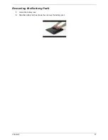
3.
Detach the front bezel out from the LCD module
4.
Disconnect the LCD power cable from here
5.
Disconnect the LCD coaxial cable from here
6.
Detach the invertor board out from the position
7.
Remove the one screw on each side to detach the LCD panel from the case
8.
Lift up the panel then take it out from the case
9.
Remove the one screw on each side to detach the antenna from the case
10.
Gently to tear the tabs that fasten the antenna cables from the case
11.
Then detach the antenna cables from the case
12.
Remove the four screws on this side to detach the left bracket
13.
Remove the four screws on another side to detach the bracke
Содержание TravelMate 4150
Страница 9: ...X Table of Contents...
Страница 14: ...Chapter 1 5 Mainboard Placement Top View...
Страница 15: ...6 Chapter 1 Bottom View...
Страница 96: ...87 Chapter 4 8 You will see the screen displaying PASS when the system has buit NAPP Master hard disc drive...
Страница 97: ...Chapter 5 88 Top View Jumper and Connector Locations Chapter 5...
Страница 98: ...89 Chapter 5 Rear View...
Страница 100: ...91 Chapter 5 VGA Board Item Description JP1 VGA Board to MB connector JP2 LCD Connector...
Страница 103: ...Chapter 5 94 Hot Swap ODD Board Item Description JP1 Hot Swap JP2 ODD device Connector...
Страница 104: ...95 Chapter 5 DVI Board Item Description JP1 DVI Board Connector...
Страница 105: ...Chapter 5 96 Clear CMOS...
Страница 107: ...98 Chapter 6 Exploded Diagram...
Страница 108: ...Chapter 6 99...
Страница 126: ...117 Appendix B...


