


14
Chapter 1
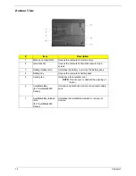
Bottom View
#
Item
Description
1
Memory compartment
Houses the computer's main memory.
2
Hard disk bay
Houses the computer's hard disk (secured by a
screw).
3
Battery release latch
Unlatches the battery to remove the battery pack.
4
Battery bay
Houses the computer's battery pack.
5
Cooling fan
Helps keep the computer cool.
NOTE:
Do not cover or obstruct the opening of
the fan.
6
AcerMedia Bay
(for TravelMate 4650
Series)
Houses an optical drive module or a second battery
pack.
7
AcerMedia Bay release
latch
(for TravelMate 4650
Series)
Unlatches the AcerMedia module for removal of
module.
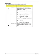
#
Icon
Item
Description
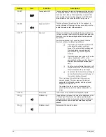
#
Item
Description
Содержание TravelMate 4150
Страница 9: ...X Table of Contents...
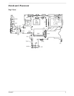
Страница 14: ...Chapter 1 5 Mainboard Placement Top View...
Страница 15: ...6 Chapter 1 Bottom View...
Страница 96: ...87 Chapter 4 8 You will see the screen displaying PASS when the system has buit NAPP Master hard disc drive...
Страница 97: ...Chapter 5 88 Top View Jumper and Connector Locations Chapter 5...
Страница 98: ...89 Chapter 5 Rear View...
Страница 100: ...91 Chapter 5 VGA Board Item Description JP1 VGA Board to MB connector JP2 LCD Connector...
Страница 103: ...Chapter 5 94 Hot Swap ODD Board Item Description JP1 Hot Swap JP2 ODD device Connector...
Страница 104: ...95 Chapter 5 DVI Board Item Description JP1 DVI Board Connector...
Страница 105: ...Chapter 5 96 Clear CMOS...
Страница 107: ...98 Chapter 6 Exploded Diagram...
Страница 108: ...Chapter 6 99...
Страница 126: ...117 Appendix B...


