28
Chapter 2
DOS Flash Utility
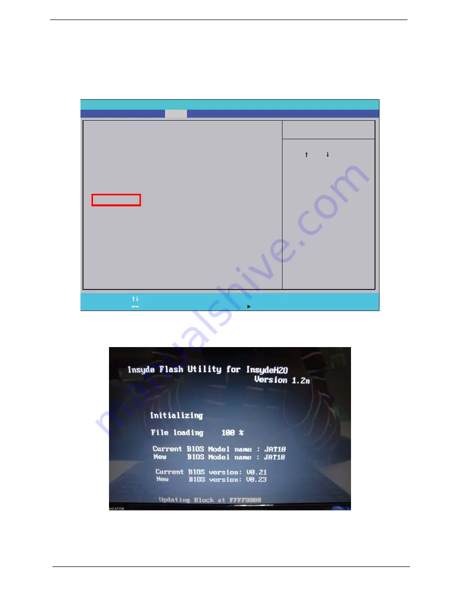
Perform the following steps to use the DOS Flash Utility:
1.
Press F2 during boot to enter the Setup Menu.
2.
Select
Boot Menu
to modify the boot priority order, for example, if using USB HDD to Update BIOS, move
USB HDD to position 1.
3.
Execute the
IFLASH.BAT
batch file to update BIOS.
The flash process begins as shown.
4.
In flash BIOS, the message
Please do not remove AC Power Source
displays.
I t e m S p e c i f i c H e l p
U s e < > o r < > t o s e l e c t
a d e v i c e , t h e n p r e s s
< F 5 > t o m o v e i t d o w n t h e
l i s t , o r < F 6 > t o m o v e
i t u p t h e l i s t . P r e s s
< E s c > t o e s c a p e t h e m e n u
F 1
E S C
H e l p
E x i t
S e l e c t I t e m
S e l e c t M e n u
C h a n g e Va l u e s
S e l e c t
S u b M e n u
E n t e r
F 9
F 1 0
S e t u p D e f a u l t
S a v e a n d E x i t
B o o t p r i o r i t y o r d e r :
1 . I D E 0 : W D C W D 5 0 0 0 B E V T - 2 2 Z A T 0
2 . I D E 2 :
3 . I D E 1 : M A T S H I T A D V D - R A M U J 8 8 0 A S
3 . U S B F D D :
4 . N e t w o r k B o o t : A t h e r o s B o o t A g e n t
5 . U S B H D D :
6 . U S B C D R O M :
B o o t p r i o r i t y o r d e r :
1 . I D E 0 : W D C W D 5 0 0 0 B E V T - 2 2 Z A T 0
2 . I D E 2 :
3 . I D E 1 : M A T S H I T A D V D - R A M U J 8 8 0 A S
3 . U S B F D D :
4 . N e t w o r k B o o t : A t h e r o s B o o t A g e n t
5 . U S B H D D :
6 . U S B C D R O M :
F 5 / F 6
I n s y d e H 2 0 S e t u p U t i l i t y R e v . 3 . 5
Main
Boot
Exit
Security
Information
Содержание AOD250
Страница 6: ...VI ...
Страница 10: ...X Table of Contents ...
Страница 28: ...18 Chapter 1 ...
Страница 45: ...Chapter 2 35 3 Execute MAC BAT to write MAC information to eeprom ...
Страница 46: ...36 Chapter 2 ...
Страница 52: ...42 Chapter 3 4 Lift the Memory cover up to remove 5 Lift the 3G cover up to remove ...
Страница 60: ...50 Chapter 3 6 Disconnect the FFC and remove the Keyboard ...
Страница 70: ...60 Chapter 3 4 Remove the WLAN Board from the Mainboard ...
Страница 78: ...68 Chapter 3 4 Lift the Thermal Module clear of the Mainboard ...
Страница 101: ...Chapter 3 91 IMPORTANT Ensure that the LCD Cable runs as shown to avoid trapping when the Bezel is replaced ...
Страница 104: ...94 Chapter 3 3 Connect the Camera cable as shown ...
Страница 113: ...Chapter 3 103 7 Run the LVDS cable along the cable channel as shown 8 Connect the LVDS cable to the Mainboard ...
Страница 126: ...116 Chapter 3 4 Replace the single screw to secure the HDD in place ...
Страница 155: ...Chapter 5 145 Power board Item Description SW1 Power button LED1 Power LED ...
Страница 208: ...Appendix A 198 ...
Страница 216: ...206 Appendix B ...
Страница 218: ...208 Appendix C ...
Страница 222: ...212 ...


