Chapter 4
127
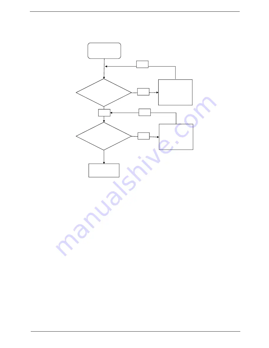
Internal Microphone Failure
If the internal
Microphone
fails, perform the following actions one at a time to correct the problem. Do not
replace non-defective FRUs:
Microphone Problems
If internal or external
Microphones
do no operate correctly, perform the following actions one at a time to
correct the problem.
1.
Check that the microphone is enabled. Navigate to
Start
´
Control
Panel
´
Hardware
and
Sound
´
Sound
and select the
Recording
tab.
2.
Right-click on the
Recording
tab and select
Show
Disabled
Devices
(clear by default).
3.
The microphone appears on the
Recording
tab.
4.
Right-click on the microphone and select
Enable
.
5.
Select the microphone then click
Properties
. Select the
Levels
tab.
6.
Increase the volume to the maximum setting and click
OK
.
7.
Test the microphone hardware:
a.
Select the microphone and click
Configure
.
b.
Select
Set up microphone
.
c.
Select the microphone type from the list and click
Next
.
d.
Follow the onscreen prompts to complete the test.
8.
If the Issue is still not resolved, see “Online Support Information” on page 207.
Start
Check M/B
Mic cable
Re-assemble
the MIC cable
to M/B
OK
NG
Check MIC
wire of LCD
module
OK
Swap MIC wire
of LCD module
OK
NG
Swap M/B
Содержание AOD250
Страница 6: ...VI ...
Страница 10: ...X Table of Contents ...
Страница 28: ...18 Chapter 1 ...
Страница 45: ...Chapter 2 35 3 Execute MAC BAT to write MAC information to eeprom ...
Страница 46: ...36 Chapter 2 ...
Страница 52: ...42 Chapter 3 4 Lift the Memory cover up to remove 5 Lift the 3G cover up to remove ...
Страница 60: ...50 Chapter 3 6 Disconnect the FFC and remove the Keyboard ...
Страница 70: ...60 Chapter 3 4 Remove the WLAN Board from the Mainboard ...
Страница 78: ...68 Chapter 3 4 Lift the Thermal Module clear of the Mainboard ...
Страница 101: ...Chapter 3 91 IMPORTANT Ensure that the LCD Cable runs as shown to avoid trapping when the Bezel is replaced ...
Страница 104: ...94 Chapter 3 3 Connect the Camera cable as shown ...
Страница 113: ...Chapter 3 103 7 Run the LVDS cable along the cable channel as shown 8 Connect the LVDS cable to the Mainboard ...
Страница 126: ...116 Chapter 3 4 Replace the single screw to secure the HDD in place ...
Страница 155: ...Chapter 5 145 Power board Item Description SW1 Power button LED1 Power LED ...
Страница 208: ...Appendix A 198 ...
Страница 216: ...206 Appendix B ...
Страница 218: ...208 Appendix C ...
Страница 222: ...212 ...


