


SuperWorkstation 5039D-I User's Manual
Chapter 4: Motherboard Connections
39
40
NIC1/NIC2 (LAN1/LAN2)
The NIC (Network Interface Controller) LED connection for LAN port 1 is located on pins 11
and 12 of JF1, and the LED connection for LAN Port 2 is on Pins 9 and 10. Attach the NIC
LED cables here to display network activity.
LAN1/LAN2 LED
Pin Definitions (JF1)
Pin#
Definition
9
NIC2 Activity LED
10
NIC2 Link LED
11
NIC1 Activity LED
12
NIC1 Link LED
HDD LED/UID Switch
The HDD LED/UID Switch connection is located on pins 13 and 14 of JF1. Attach a cable to
Pin 14 to show hard drive activity status. Attach a cable to Pin 13 to use UID switch. Refer
to the table below for pin definitions.
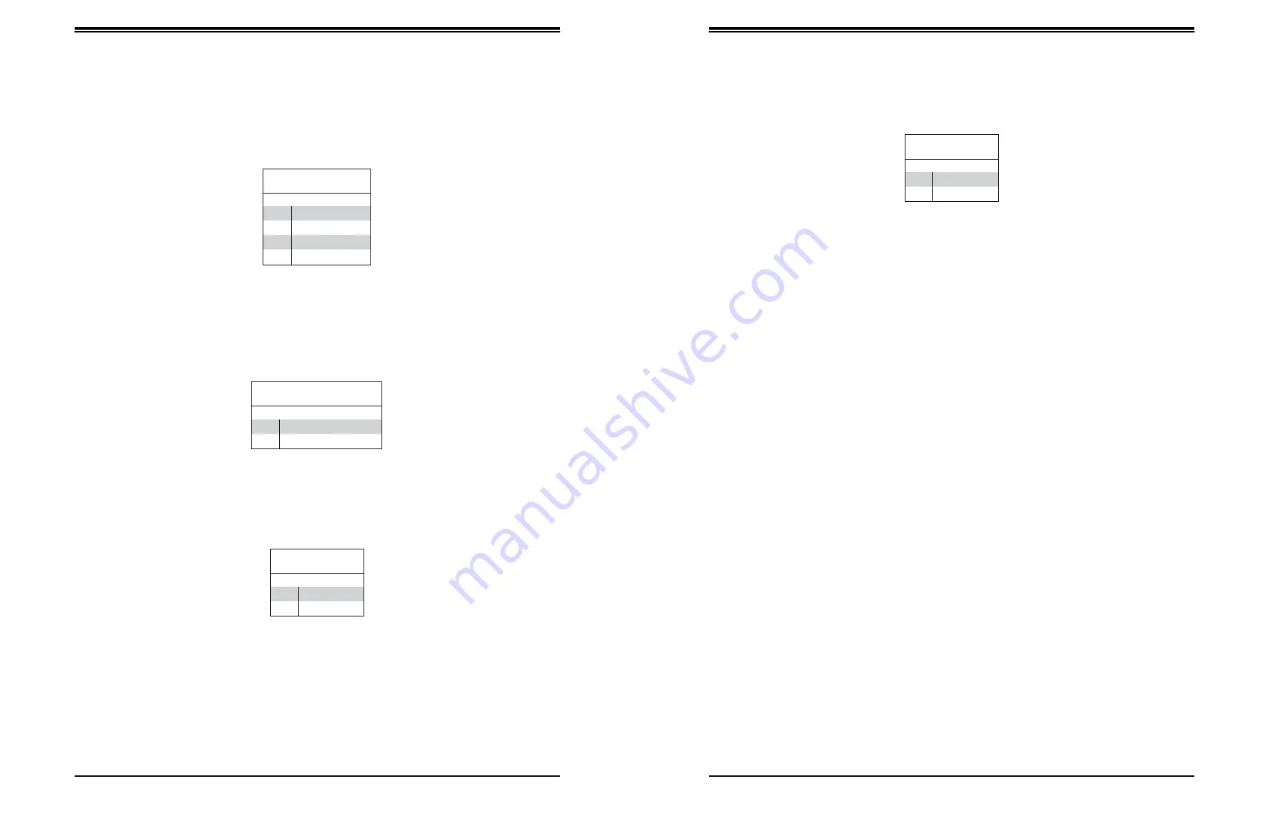
NMI Button
The non-maskable interrupt button header is located on pins 19 and 20 of JF1.
NMI Button
Pin Definitions (JF1)
Pin#
Definition
19
Control
20
Ground
Data Cables
The data cables in the system have been carefully routed to maintain airflow efficiency. If
you disconnect any of these cables, take care to re-route them as they were originally when
reconnecting them.
Important!
Make sure the the cables do not come into contact with the fans.
HDD LED
Pin Definitions (JF1)
Pin#
Definition
13
3.3V Standby/UID Switch
14
HDD Active
Power LED
The Power LED connection is located on pins 15 and 16 of JF1.
Power LED
Pin Definitions (JF1)
Pin#
Definition
15
3.3V
16
Power LED


