


SuperWorkstation 5039D-I User's Manual
Chapter 4: Motherboard Connections
37
38
Control Panel
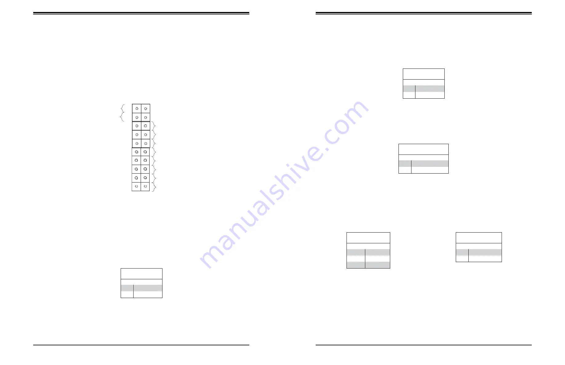
JF1 contains header pins for various control panel connections. See the figure below for the
pin locations and definitions of the control panel buttons and LED indicators.
All JF1 wires have been bundled into a single cable to simplify this connection. Make sure
the red wire plugs into pin 1 as marked on the motherboard. The other end connects to the
control panel PCB board.
Reset Button
The Reset Button connection is located on pins 3 and 4 of JF1. Attach it to a hardware reset
switch on the computer case.
1
Power Button PWR
Reset Button Reset
P3V3
2
Ground
Ground
Power Fail LED
Power Fail LED
The Power Fail LED connection is located on pins 5 and 6 of JF1.
UID LED
OH/Fan Fail LED
P3V3_STBY
P3V3_STBY
P3V3_STBY/ID_UID_SW
P3V3
NC
NIC2 Link Active LED
NIC1 Link Active LED
HDD LED
FP PWRLED
NC
SW_NMI_N
19
20
Ground
Overheat (OH)/Fan Fail
Figure 4-1. JF1: Control Panel Pins
Connect an LED cable to pins 7 and 8 of JF1 to use the Overheat/Fan Fail LED connections.
The LED on pin 8 provides warnings of overheat or fan failure.
Power Button
The Power Button connection is located on pins 1 and 2 of JF1. Momentarily contacting both
pins will power on/off the system. This button can also be configured to function as a suspend
button (with a setting in the BIOS - see Chapter 7). To turn off the power when the system
is in suspend mode, press the button for 4 seconds or longer.
Power Button
Pin Definitions (JF1)
Pin#
Definition
1
Signal
2
Ground
Reset Button
Pin Definitions (JF1)
Pin#
Definition
3
Reset
4
Ground
Power Fail LED
Pin Definitions (JF1)
Pin#
Definition
5
3.3V
6
PWR Supply Fail
OH/Fan Fail Indicator
Status
Status
Definition
Off
Normal
On
Overheat
Flashing
Fan Fail
OH/Fan Fail LED
Pin Definitions (JF1)
Pin#
Definition
7
Blue LED
8
OH/Fan Fail LED


