Getting Started
37
2.11.3 Dummy Carrier Modules
Any unused drive bays must be fitted with a dummy carrier module.
2.11.4 Engaging the Anti-tamper Locks
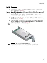
The anti-tamper locks are fitted in the drive carrier handles and are accessed through the small
cutout in the latch section of the handle.
Drives are supplied with the locks set in the locked position.
2.11.4.1 Activating the Locks
1
Carefully insert the lock key provided into the cutout in the handle.
2
Locate the key into its socket.
3
Rotate the key in a clockwise direction until the indicator is visible in the aperture beside the key.
).
4
Remove the key.
De-activation is the reverse of this procedure, that is:
• Rotate the key in a anti-clockwise direction until the indicator is no longer visible in the
aperture beside the key.
Note
A drive carrier cannot be installed if its anti-tamper lock is activated outside the Enclosure.
2.12 Power Cord Connection
2.12.1 Parts Check List
• Power cord to requisite local standards
Figure 2–16
Activating the Anti-tamper Lock
Содержание Altos S205F
Страница 11: ...Preface xi Revision History Version Date Description of Change 1 0 1 May 2004 Initial Release ...
Страница 12: ...Acer S205F S200F User s Manual xii ...
Страница 54: ...Acer S205F S200F User s Manual 42 ...
Страница 58: ...Acer S205F S200F User s Manual 46 v Visible and Audible Alarms 13 ...


