172
Chapter 5
BIOS Recovery by Crisis Disk
BIOS Recovery Boot Block:
BIOS Recovery Boot Block is a special block of BIOS. It is used to boot up the system with minimum BIOS
initialization. Users can enable this feature to restore the BIOS firmware to a successful one once the previous
BIOS flashing process failed.
BIOS Recovery Hotkey:
The system provides a function hotkey:
Fn+Esc
, for enable BIOS Recovery process when system is powered
on during BIOS POST. To use this function, it is strongly recommended to have the AC adapter and Battery
present. If this function is enabled, the system will force the BIOS to enter a special BIOS block, called Boot
Block.
Steps for BIOS Recovery by Crisis Disk:
Before doing this, one Crisis Disk should be prepared ready in hand. The Crisis Disk could be made by
executing the Crisis Disk program in another system with Windows XP OS.
Follow the steps below:
1.
Plug in the USB Floppy Disk.
2.
Copy
kblg009.wph
to the tool’s folder and rename it as
BIOS.wph
. Execute
wincris.exe
.
3.
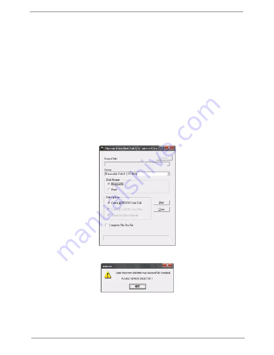
Select the
Removable
option for Disk Format and click
Start
. Follow the instructions on the screen.
4.
Click
Format
to format and create the disk.
5.
A message on the screen shows when the crisis recovery disk has been created.
To use the crisis recovery disk, do the following:
1.
Plug in the USB Flash Disk without AC plug.
2.
Press
Fn + Esc
and then plug in AC power while holding down the keys. Power button flashes orange.
3.
Press
Power
button and system will enter crisis mode to flash the BIOS.
4.
Update to the latest version BIOS for the system using the regular BIOS flashing process.
Содержание 4535 5133 - Aspire - Athlon X2 2.1 GHz
Страница 6: ...VI ...
Страница 44: ...Chapter 2 35 A progress screen displays ...
Страница 49: ...40 Chapter 2 2 In DOS mode run the MAC BAT file to write MAC values to eeprom ...
Страница 56: ...Chapter 3 47 5 Remove the HDD Cover as shown ...
Страница 70: ...Chapter 3 61 5 Disconnect the speaker cable as shown and remove the Speaker from the Upper Cover ...
Страница 98: ...Chapter 3 89 4 Lift the bezel away from the panel ...
Страница 101: ...92 Chapter 3 4 Lift the LCD Panel out of the casing as shown ...
Страница 114: ...Chapter 3 105 3 Connect fan cable to the mainboard as shown Step Size Quantity Screw Type Thermal Module M 2 5 3 2 4 ...
Страница 125: ...116 Chapter 3 4 Replace the single securing screw ...
Страница 147: ...138 Chapter 3 ...
Страница 194: ...Chapter 6 185 ...
Страница 219: ...Appendix A 210 ...
Страница 249: ...240 Appendix B ...
Страница 251: ...242 Appendix C ...


