100
Chapter 3
7.
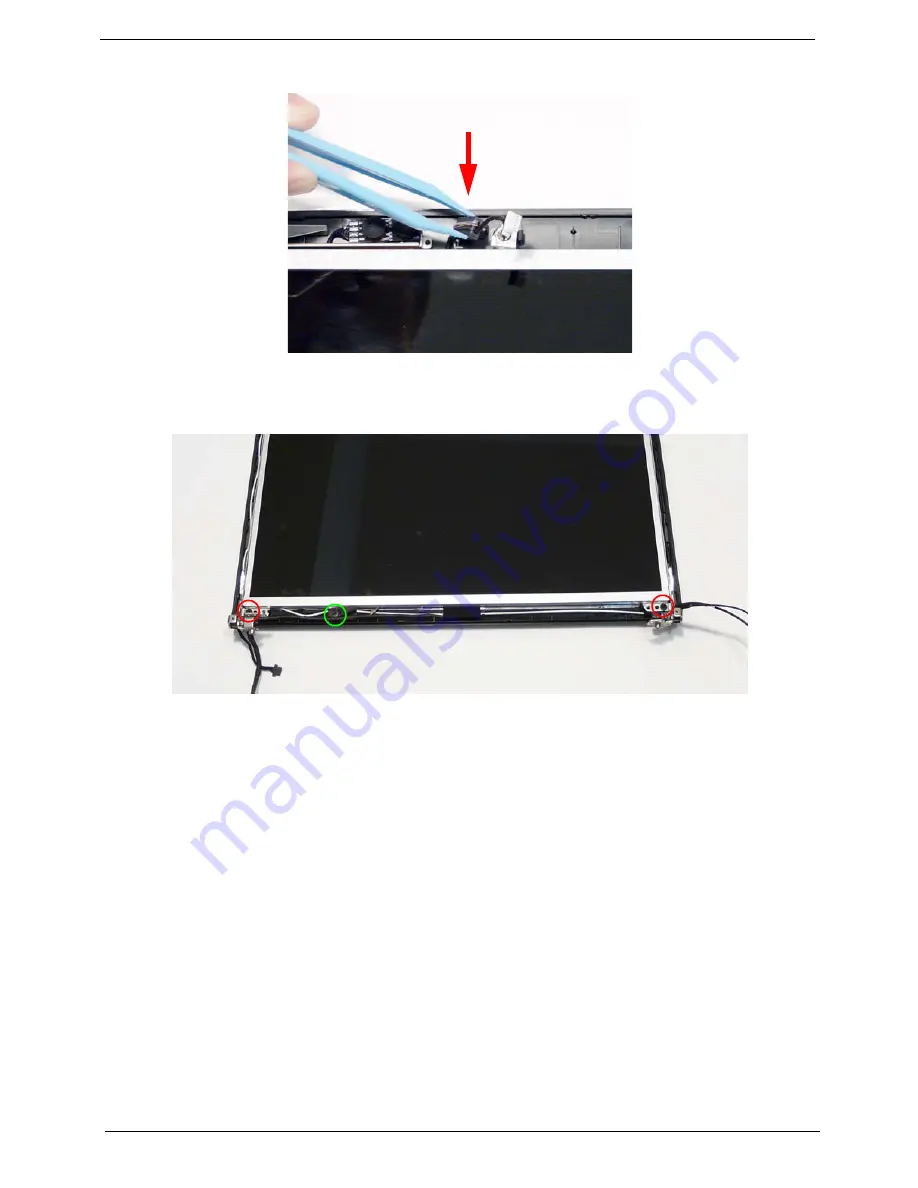
Replace the Camera Module cable bundle in the casing as shown.
8.
Replace the three screws to secure the panel and grounding within the LCD module.
IMPORTANT:
When replacing the screws in the LCD brackets (red callout) do not use the screw holes marked
with ‘X’. These slots are reserved for the Bezel securing screws.
Содержание 4535 5133 - Aspire - Athlon X2 2.1 GHz
Страница 6: ...VI ...
Страница 44: ...Chapter 2 35 A progress screen displays ...
Страница 49: ...40 Chapter 2 2 In DOS mode run the MAC BAT file to write MAC values to eeprom ...
Страница 56: ...Chapter 3 47 5 Remove the HDD Cover as shown ...
Страница 70: ...Chapter 3 61 5 Disconnect the speaker cable as shown and remove the Speaker from the Upper Cover ...
Страница 98: ...Chapter 3 89 4 Lift the bezel away from the panel ...
Страница 101: ...92 Chapter 3 4 Lift the LCD Panel out of the casing as shown ...
Страница 114: ...Chapter 3 105 3 Connect fan cable to the mainboard as shown Step Size Quantity Screw Type Thermal Module M 2 5 3 2 4 ...
Страница 125: ...116 Chapter 3 4 Replace the single securing screw ...
Страница 147: ...138 Chapter 3 ...
Страница 194: ...Chapter 6 185 ...
Страница 219: ...Appendix A 210 ...
Страница 249: ...240 Appendix B ...
Страница 251: ...242 Appendix C ...


