SP8016-1005
ACCU-STEAM SERVICE MANUAL
PAGE 9
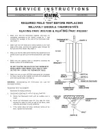
hI-LIMIT ASSEMBLy
Is a safety designed to turn off the griddle at a preset temperature to limit the pressure of the
steam chamber so that it doesn’t set off the one time pressure relief valve which will render
the griddle un-repairable
Unplug the unit.
1.
Remove the Hi-Limit access cover located under the griddle.
2.
Verify the hi Limit rod has
pulled and released the switch before proceeding.
Remove the switch bracket and assembly by first removing the two nuts. Be careful not to lose
3.
any of the parts located underneath.
Note: The entire assembly will want to drop down when removing the bracket.
Replace the rod, solder washer, flat washer and the spring. Put the two washers on the studs
4.
and reattach the switch bracket
Note: It is extremely important that the solder washer has good surface contact with the
surface of the thermal-well. Make sure the solder washer is installed before the flat washer.
Reattach the spring and access cover.
5.
See the drawing on the following page.
TIME DELAy RELAy
The time delay relay is used to delay a signal to allow for the proper mixture of air and gas
before igniting the main burners.
Unplug the unit
1.
Remove the three screws from the front door panel and drop the panel down.
2.
Remove the mounting screw in the middle of the relay and the two wires.
3.
Reinstall in reverse order.
4.
Note: Make sure the adjustment pot is set for 20 seconds.
RELAy, TIME DELAy
AT2h-2500
TIME DELAy ADjUSTMENT
SET FOR 20 SECONDS
SOLDER WAShER
AT2M-2860-1
WAShER
AT2F-1367-1
ROD
AT2M-2861-1
MICROSWITCh
COVER
AT2E-1759
COMPRESSION
SPRING
AT2h-1365-1
EXTENSION
SPRING
AT2h-1640-1
BRACKET, SWITCH
AT2M-1558
MICROSWITCh
AT2E-1639-1
REMOVAL AND INSTALLATION