


Prepared By: Peter Brandt Version: 08 – 20080415
Page
11 of 26
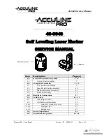
40-6640 Service Manual
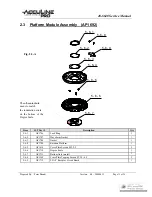
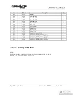
Item
JLT Part #
Description
Qty
5-5-1
AP1696
Cross Plate Screws M2x10
2
5-5-2
AP1697
M2 Lock Washers
2
5-5-3
AP1698
Support Post Type A (w. 1 hole through side of post)
2
5-5-4
AP1699
Support Post Type B (w. 2 holes through side of post)
2
5-5-5
AP1700
Locking Ring
1
5-5-6
AP1701
Compression Springs
2
5-5-7
AP1702
Crank Shaft
1
5-5-8
AP1703
Magnets: 10 mm x 4 mm
4
5-5-9
AP1704
Fixture Support
1
5-5-10
AP1705
Base Plate
1
5-5-11
AP1677
Cross Plate Tapping Screws ST 2.9x8
3
5-5-12
AP1658
M3 Lock Washers
4
5-5-13
AP1513
Cross Plate Screws M3x8
4
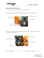
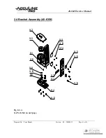
General Assembly Instructions
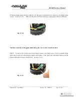
1.
Attach Support Post Type B (5-5-4) to Base Plate (5-5-10) using Cross Plate Tapping Screws (5-5-13).
Make sure that concave impression of plate is facing up with indentation of plate to the right side of the two
posts (when looking down upon the plate).
2.
Attach Support Post Type A (5-5-3) to other remaining holes in Base Plate (5-5-10) using Cross Plate Tapping
Screws (5-5-13).
3.
Insert Crank Shaft (5-5-7) through inside the matching opening in Fixture Support (5-5-9). Make sure that
grease is applied to Crank Shaft. Set Crank Shaft in uppermost position.
4.
Place Fixture Support (5-5-9) onto Base Plate (5-5-10) so that it fits among the four support posts. The
Crank Shaft should be oriented between the two Type B Support Posts (5-5-4). Secure the Fixture Support
from below the Base Plate using the three Cross Plate Tapping Screws (5-5-11).
5.
Place the four Magnets (5-5-8) in the four matching openings of the Fixture Support (5-5-9). The magnets
will attach themselves to the Base Plate (5-5-10) below.
6.
Place Locking Ring (5-5-5) down upon Type B Support Posts (5-5-4). Make sure that Locking Ring fits in
place with Crank Shaft (5-5-7).
7.
Slide the two Compression Springs (5-5-6) over each of the Type B Support Posts (5-5-4). Push the
Compression Springs down far enough to insert the Cross Plate Screws (5-5-1) and Lock Washers (5-5-2).
Screw both screw in all the way and then release the Spring.
The Base Plate Module can be disassembled using the reverse order described above.


