Prepared By: Peter Brandt Version: 08 – 20080415
Page
4 of 26
40-6640 Service Manual
3.
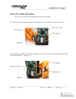
Before moving the Front and Back Housing units in place, position the Rubber Jacket (8) over the instrument
so that the matching hole is located over the Crank Shaft and the on-off indicator light (from the Power Switch
Circuit Board) is through a smaller hole in Rubber Jacket. (See Fig. 1 D.)
Front Housing
Back Housing
Indicator light
Crank Shaft
Fig. 1-D
4.
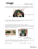
Now bring both Front and Back Housing units together over the edges of the Rubber Jacket. Use the four
Cross Plate Screws (2) to secure the units. [Note: It may be necessary to use a thin nail placed into the screw
holes to center the nuts found inside the instrument so that a straight path is achieved for the screws.]
5.
Holding the instrument up-side- down, further secure the housing units using the four Cross Plate Screws (1).
Rotate the bottom portion of the base in order to locate the screw holes through the access hole. Drop the
screws into the hole and screw into housing units until tight. [Note: It may be necessary to use a thin nail
placed into the screw holes to center the nuts found inside the instrument so that a straight path is achieved for
the screws.]
The instrument can be disassembled using the reverse order described above.

