Prepared By: Peter Brandt Version: 08 – 20080415
Page
7 of 26
40-6640 Service Manual
4.
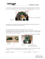
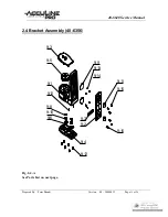
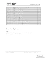
Now attach the connecting circuit board to the underside of the supporting plate of the Core Module (5-3).
The two bolts on the underside must first be removed and then used to attach the circuit board. See Fig. 1-1-D.
Nuts for securing circuit board
Fig. 1-1-D
5.
Connect plug (Fig. 1-1-B) to the top connection on found on the back side of the Main Circuit Board (5-10).
See Electrical Connections figure in Section 3 for further help.
6.
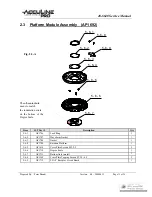
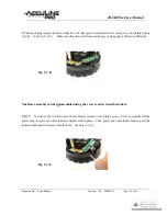
First connect the plug from the A/C Receptor Circuit Board (item 5-6-9 of section 2.3)
to the middle front connection of the Main Circuit Board. Then attach the Main Circuit Board (5-10) to the
Base Plate Module (5-5) using the three Cross Plate Tapping Screws (5-9). See Fig.1-1-F. Also see Electrical
Connections figure in Section 3 for further help.
Connected Plug (from Connecting Circuit Board)
Fig. 1-1-E
Fig. 1-1-F
Connected Plug from
A/C Receptor Circuit Board
7. Now attach the Alarm Loop Circuit Board to the top of the Support Seat Ring (5-2) using the three Cross Plate
Tapping Screws (5-12). The alarm loop must fit around the alarm rid. See Fig. 1-1-G.

