


M 0495
-
4
2
6
4
5
3
2
1
GB
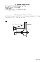
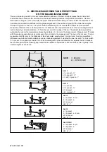
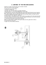
3 - ASSEMBLY OF THE PIEZO MEASURERS
Problems of excessive compensation and out-of-phase sometimes depend on a fault in the piezo measurers.
To replace them, proceed as follows:
1. Remove the weight shelf.
2. Remove nuts 1 and 2 with relative cup springs and washers.
3. Back-off screws 3, 4, 6 and 5 then disassemble the various parts.
4. Reassemble the various parts without tightening the nuts being careful to follow the correct sequence.
N.B.: Mount the piezo units in accordance with the position of the coloured wires shown in the drawing.
5. Keeping the spindle perfectly aligned, tighten the nuts 5 and 6 with a spanner, and nuts 3 and 4 by hand (by half a
turn with the spanner if necessary).
6. Refit the washers, cup springs and nuts 1 and 2. Tighten the nuts fully in order to fully regain the elasticity of the cup
springs, then loosen them by half a turn. This will automatically ensure correct preloading on the piezo (a torque
wrench can be used set to 400 kg. cm.).
7. Cover the piezo units with a generous layer of silicone.(
N.B.: For correct operation, insulation of the piezo
crystals should be greater than 50 Mohm
).
8. Reassemble the various parts.
9. Again carry out the automatic calibration.
yellow
blue
yellow
white
Содержание 1250
Страница 1: ...SERVICE MANUAL MODELS 1250 1450 1550 1650 1850...
Страница 2: ......
Страница 3: ...Model 1250 Wheel Balancer...
Страница 5: ...M 0495 2 GB...
Страница 9: ...M 0495 6 3 GB 5 POWER SUPPLY LAYOUT DIAGRAM 230 V connection...
Страница 10: ...M 0495 7 4 GB 6 REPLACING THE POWER BOARD check voltage...
Страница 14: ......
Страница 15: ...Model 1450 Wheel Balancer...
Страница 17: ...M 0492 2 GB...
Страница 30: ......
Страница 31: ...Model 1550 Wheel Balancer...
Страница 33: ...M 0493 2 GB...
Страница 40: ...M 0493 9 5 GB 6 POWER SUPPLY LAYOUT DIAGRAM...
Страница 41: ...M 0493 10 6 GB 7 TO REPLACE POWER BOARD...
Страница 46: ......
Страница 47: ...Model 1650 Vibration Control Diagnostic System...
Страница 49: ...M 0494 2 GB...
Страница 55: ...M 0494 8 5 GB 7 POWER SUPPLY LAYOUT DIAGRAM...
Страница 56: ...M 0494 9 6 GB 8 TO REPLACE POWER BOARD...
Страница 62: ......
Страница 63: ...Model 1850 Wheel Balancer...
Страница 65: ...M 0496 GB 2...
Страница 76: ...SERVICE MANUAL MODELS 1250 1450 1550 1650 1850...