


1
M 0496 GB
-
3
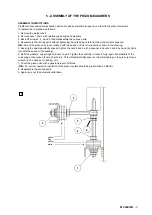
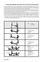
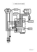
1 - TO CHANGE SUPPLY VOLTAGE
(See recommended spare lists and power layout diagram)
The machine can run on 115 V - 50/60 Hz or 230 V - 50/60Hz.
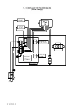
To change the supply voltage, proceed as follows:
1) Replace the motor.
2) Replace the entire power board or else modify the board as follows:
A) Replace the capacitor
B) Replace the transformer
C) Replace the solenoid group
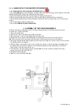
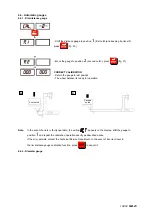
2 - CHECKING OF THE RIM DISTANCE GAUGE
Check that the ruler used for measuring the DISTANCE of the wheels reads 265 mm as measurement of the distance
from the adapter plane UC200. If the graduates scale is changed, position it with the line indicating 265 at the fixed
index limit (reading point) when the gauge tip coincides with the adapter plane.
Reading point: 265 mm
Adapter plane
Содержание 1250
Страница 1: ...SERVICE MANUAL MODELS 1250 1450 1550 1650 1850...
Страница 2: ......
Страница 3: ...Model 1250 Wheel Balancer...
Страница 5: ...M 0495 2 GB...
Страница 9: ...M 0495 6 3 GB 5 POWER SUPPLY LAYOUT DIAGRAM 230 V connection...
Страница 10: ...M 0495 7 4 GB 6 REPLACING THE POWER BOARD check voltage...
Страница 14: ......
Страница 15: ...Model 1450 Wheel Balancer...
Страница 17: ...M 0492 2 GB...
Страница 30: ......
Страница 31: ...Model 1550 Wheel Balancer...
Страница 33: ...M 0493 2 GB...
Страница 40: ...M 0493 9 5 GB 6 POWER SUPPLY LAYOUT DIAGRAM...
Страница 41: ...M 0493 10 6 GB 7 TO REPLACE POWER BOARD...
Страница 46: ......
Страница 47: ...Model 1650 Vibration Control Diagnostic System...
Страница 49: ...M 0494 2 GB...
Страница 55: ...M 0494 8 5 GB 7 POWER SUPPLY LAYOUT DIAGRAM...
Страница 56: ...M 0494 9 6 GB 8 TO REPLACE POWER BOARD...
Страница 62: ......
Страница 63: ...Model 1850 Wheel Balancer...
Страница 65: ...M 0496 GB 2...
Страница 76: ...SERVICE MANUAL MODELS 1250 1450 1550 1650 1850...