


M 0493 -
5
GB
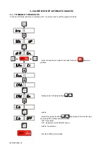
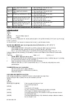
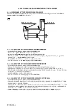
3.2 - CALIBRATION OF THE DISTANCE POTENTIOMETER
- Remove the weight shelf and refit the tip on the gauge rod.
- Back-off the screws fastening the pulley on the potentiometer shaft.
- Select on the FUNCTIONS MENU (
CONTROL OF THE FUNCTIONS MENU
)
→
SET UP
→
AUTODIAGNOSTIC
(
SELF-DIAGNOSTICS
)
- Scroll until the wording
(diS)
appears on the left display while a number appears on the right display, which varies
when the distance gauge is moved and represents a reference for calibrating the potentiometer.
- With the gauge fully retracted, turn the potentiometer shaft keeping the pulley still until a number between 50 and
100 is read.
- Decrease by two numbers, then retighten the screws to secure the pulley on the shaft.
Carry out the DISTANCE GAUGE SET UP (
RIM DISTANCE GAUGE
);
3.3 - CALIBRATION OF THE DIAMETER POTENTIOMETER
- After
CALIBRATION OF THE DISTANCE POTENTIOMETER
press
- The wording
[dIA]
appears on the left display, a number appears on the right display, which varies when the gauge
is turned and represents a reference for calibrating the potentiometer.
- Remove the diameter gauge from the gauge rod after backing off relative screw.
- Slightly pull out the gauge rod and rest its stop on the machine shaft in external position near the base.
- Turn the potentiometer shaft until a number between 50 and 100 is read, then place it back in its correct work
position.
- Lock the potentiometer with relative set screw
- Carry out the DIAMETER GAUGE SET UP (
DIAMETER GAUGE
)
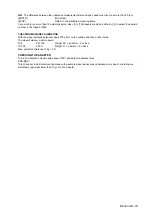
3.4 - CALIBRATION WIDTH SONAR (OPTIONAL)
- After
DIAMETER POTENTIOMETER CALIBRATION
press
.
- Place a flat surface at least 12 cm from the width Sonar and check that there are variations in the number displayed.
- If on control, after having performed calibration, a measurement inaccuracy is found greater than 1/2”, repeat the
calibration modifying the distance value between the distance gauge and the sensor (tolerance ± 1" from the measu-
rement found manually) until a correct width value is obtained.
Содержание 1250
Страница 1: ...SERVICE MANUAL MODELS 1250 1450 1550 1650 1850...
Страница 2: ......
Страница 3: ...Model 1250 Wheel Balancer...
Страница 5: ...M 0495 2 GB...
Страница 9: ...M 0495 6 3 GB 5 POWER SUPPLY LAYOUT DIAGRAM 230 V connection...
Страница 10: ...M 0495 7 4 GB 6 REPLACING THE POWER BOARD check voltage...
Страница 14: ......
Страница 15: ...Model 1450 Wheel Balancer...
Страница 17: ...M 0492 2 GB...
Страница 30: ......
Страница 31: ...Model 1550 Wheel Balancer...
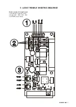
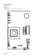
Страница 33: ...M 0493 2 GB...
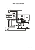
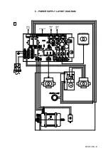
Страница 40: ...M 0493 9 5 GB 6 POWER SUPPLY LAYOUT DIAGRAM...
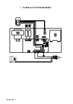
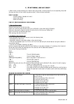
Страница 41: ...M 0493 10 6 GB 7 TO REPLACE POWER BOARD...
Страница 46: ......
Страница 47: ...Model 1650 Vibration Control Diagnostic System...
Страница 49: ...M 0494 2 GB...
Страница 55: ...M 0494 8 5 GB 7 POWER SUPPLY LAYOUT DIAGRAM...
Страница 56: ...M 0494 9 6 GB 8 TO REPLACE POWER BOARD...
Страница 62: ......
Страница 63: ...Model 1850 Wheel Balancer...
Страница 65: ...M 0496 GB 2...
Страница 76: ...SERVICE MANUAL MODELS 1250 1450 1550 1650 1850...