Accu-Sort
®
Systems, inc.
511 School House Road
Telford, PA 18969 U.S.A.
1-800-BAR-CODE
1-(215)-723-0981
This copy expires 7 days after: 8/25/06
unless stamped "CONTROLLED
COPY" in red
Issued: 07/06/05
Revised:
TP-ENM-704
Rev.
A
Page 16 of 22
Annotations to this document are acceptable only if done in RED pen and initialed by a
representative of the department responsible for the creation and maintenance of the document
RFR-02 READER TEST PROCEDURE
______________________________________________________________________________
THIS IS A CONTROLLED COPY ONLY IF STAMPED “CONTROLLED COPY” IN RED.
©
Accu-Sort Systems, inc.
7.44
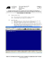
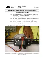
Remove tag and repeat step 7.42, Procomm should display 2NO TAG and the LED
connected between the yellow wire and the power supply should light. Note the blue LED
on the lid should not light.
7.45
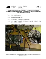
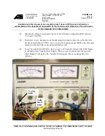
Connect Blue jumper wire between common of power supply and pin 5 of the test header.
7.46
Connect Yellow wire to +25V of power supply and tap pin 3 of test header, for every tap
you should again get 20000 on the Procomm display and the blue LED on the lid should
flash. This test evaluates the Isolated input of RFR-02’s Input 2.
7.47
If steps 7.42 through 7.46 pass, the RFR-02’s Input 2 and the Outputs are deemed
functional. Record as passed.
7.48
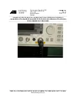
Move the BNC cable from antenna 2 to antenna 1 and move test connector from input 2 to
input 1 on the RFR-02.
7.49
Repeat steps 7.42 through 7.47 with the only difference being that Procomm will show
10000 with a tag in the field and 1NO TAG when the tag is removed from the antenna field.
7.50
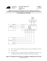
To Test RS232 + RS422 Network Port.


