17
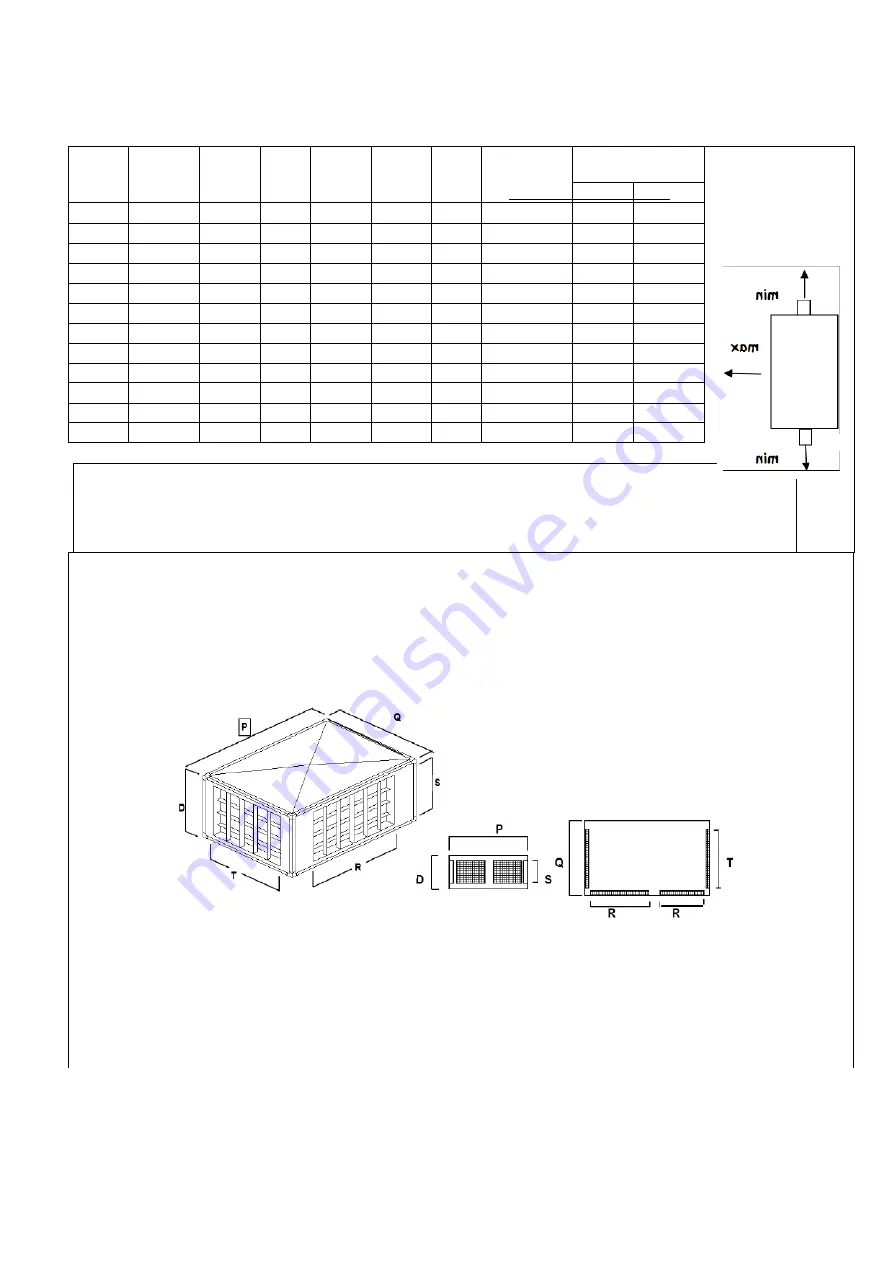
STANDARD HEAD FOR DIRECT AIR DISTRIBUTION WARM AIR HEATERS OF THE
"
AS COND EX
"
Air blown and dimensions in mm
with horizontal and vertical fin vents on three sides of the nozzles.
MOD.
P
Q
D
R
T
S
n° of nozzles
(1)
Air blown in m.
max 2)
min
50
825
591
305
300
300
200
1+1+1
16
16
65
825
591
305
300
300
200
1+1+1
16
16
80
935
665
405
550
550
300
1+1+1
34
34
100
935
665
405
550
550
300
1+1+1
38
38
150
1355
935
405
750
750
300
1+1+1
55
55
175
1355
935
405
750
750
300
1+1+1
60
60
200
1355
935
405
750
750
300
1+1+1
63
63
250
1355
935
405
750
750
300
1+2+1
74
60
300
1355
935
405
750
750
300
1+2+1
80
62
425
2215
1255
405
650
750
300
1+3+1
90
69
500
2215
1255
405
650
750
300
1+3+1
94
72
600
2215
1415
405
650
750
300
1+3+1
102
84
1) Short side (Q) + long side (P) + short side (Q).
2) The final speed of the blown air is 0.15 m/sec, and the nozzle fins’ deflection is 0°.
If deflection = 30°, multiply the blown air value by 0.65.
Содержание AS COND
Страница 39: ...39 ELECTRICAL DIAGRAMS AS COND EX...
Страница 40: ...40 AS COND 80 100 150 175 200...
Страница 41: ...41 AS COND EX 250...
Страница 42: ...42 AS COND 300 600...
Страница 52: ...52...
Страница 53: ...53...
Страница 54: ...54...
Страница 55: ...55...


