ACCES I/O Products, Inc.
MADE IN THE USA
mPCIe- and M.2-AIO16-16F Family Manual
6
Rev B7a
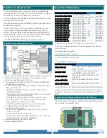
Note *: These registers are only functional on the FDS models.
All these registers can be operated from any operating system using any programming language, using either no driver at all (kernel mode, Linux ioperm(3), DOS, etc.) or using one of the
ACCES provided drivers (AIOWDM / AIOAIO [for Windows], APCI [for Linux & OSX]), or using any 3
rd
party APIs such as provided with Real-Time OSes. Addresses not explicitly documented
are reserved and should not be accessed.
REGISTER DETAILS
Register bits labeled UNUSED or RSV are reserved and should be cleared to zero in all write operations and ignored in all read operations.
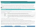
Resets and Power, 0 of 64-bit Memory BAR[2+3] Read/Write 32-bits only
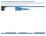
bit D31 THROUGH D7
D6
D5
D4
D3
D2
D1
D0
Name UNUSED
RST FIFO
RST DIO
UNUSED
RST DAC
PD ADC
RST ADC
RST BOARD
RST FIFO:
Writing with bit D6 set will reset the ADC FIFO, returning it to the power-on / reset state: emptying the FIFO by throwing away the contents.
RST DIO:
Writing with bit D5 set will reset the Digital I/O circuits to their power-on / reset state: returning all I/O Groups to input mode and disabling secondary
functions.
RST DAC:
Writing with bit D3 set will reset the Analog Output circuits to their power-on / reset state: ±10V range on all DAC outputs with 0V on each output.
PD ADC:
Writing a 1 will power the ADAS3022 down. Write a 0 to power the ADAS3022 back up. Only this bit does not auto-clear to zero on write.
RST ADC:
Writing a 1 will reset the Analog Input circuits to their power-on / reset state: see each ADC Register for more details
RST BOARD:
Writing a 1 will reset the entire device to its power-on / reset state.
All RST bits are “command” bits: a 1 causes the reset to occur, and the reset clears the 1.
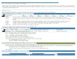
DAC Control, 4 of 32-bit Memory BAR[1]Read/Write 32-bits only
bit D31
D30
D29
D28
D27-D24 D23 through D20 D19 through D16
D15 through D0
Name DAC SPI busy unused DAC Waveform Running DAC FHE unused
C3 C2 C1 C0 A3 A2 A1 A0
16-bit DAC Counts (0-FFFF)
Bits 31, 29, and 28 are read-only. Bits 29 and 28 only exist on the FDS models.
Bit 31: If set the DAC SPI bus is busy; avoid writing to +4 while this bit is set
Bit 29: If set the DAC Waveform Playback is in-process
Bit 28: If set the DAC Waveform FIFO is less than half full
Please refer to the LTC2664 Data Sheet for details regarding bits D23-D0
Consult the AIOAIO Software Reference, or our sample programs’ source, to avoid the hassle:
DAC_SetRange1(iBoard, iChannel, iRange);
DAC_OutputV(iBoard, iChannel, double Voltage);
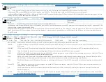
DAC Waveform Rate Divisor, 8 of 32-bit Memory BAR[1]Read/Write 32-bits only
Write a 32-bit divisor to control the speed at which DAC Waveform playback occurs (Points per second). Each timeout of this clock causes the DACs to simultaneously output the
last loaded values; the FPGA then writes the next Point from the DAC Waveform FIFO to the DAC chip. A Point consists of 1, 2, 3, or 4 DAC control words as specified at +54.
DAC Waveform Rate Divisor = integer(Base Clock ÷ Target DAC Waveform Output Rate)
Actual DAC Waveform playback (Points/second) Rate (Hz) = Base Clock ÷ DAC Waveform Rate Divisor
FDS models only
Base Clock, C of 32-bit Memory BAR[1]Read Only 32-bits only


