background image

16

Technical Information

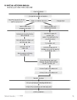
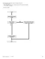
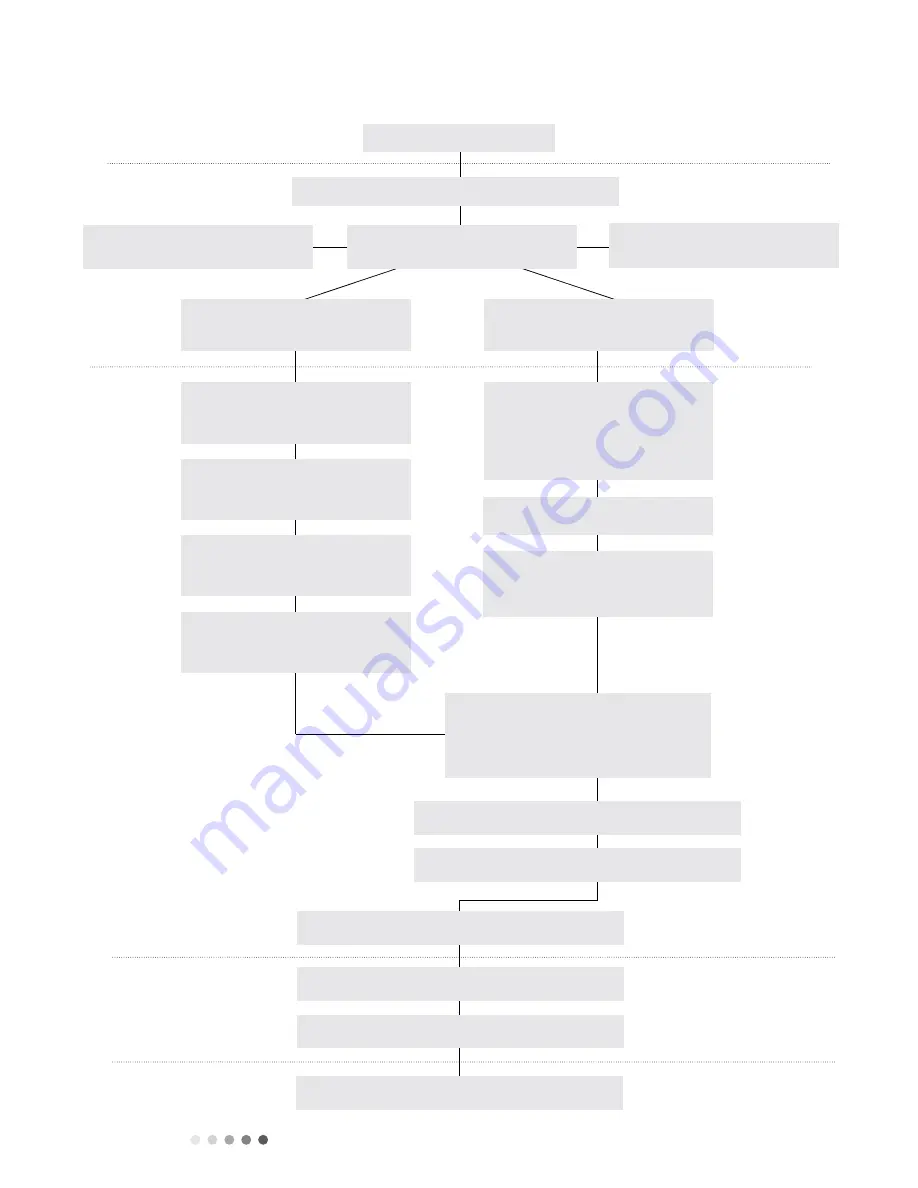
Start installation

Preparation before installation

Read the requirements for 

electric connection

Select installation location

Prepare tools

Select indoor unit 

installation location

Select outdoor unit 

installation location

Install wall-mounting frame, 

drill wall holes

Connect pipes of indoor unit 

and drainage pipe

Connect wires of 

indoor unit

Bind up pipes and hang 

the indoor unit

Install the support of 

outdoor unit

(select it according to the 

actual situation)

Fix outdoor unit

Make the bound pipes pass 

through the wall hole and then 

connect outdoor unit

Install drainage joint of 

outdoor unit (only for cooling 

and heating unit)

Connect pipes of outdoor unit

Connect wires of outdoor unit

Neaten the pipes

Vacuum pumping and leakage detection

Check after installation and test operation

Finish installation

8. INSTALLATION MANUAL

     INSTALLATION PROCEDURE

Содержание AWHD(18)ND3GO

Страница 1: ...AC Pro Multi Zone Outdoor 18 24K Service Manual AWHD 18 ND3GO AWHD 24 ND3GO Refrigerant R410A ...

Страница 2: ......

Страница 3: ...nstalling the Outdoor Unit 18 8 3 Installation Dimension Diagram 19 8 4 Check after Installation 20 9 Troubleshooting 21 9 1 Flashing LED of Indoor Outdoor Unit and Primary Judge ment 21 9 2 Malfunction Checking and Elimination 22 9 3 Maintenance Method for Normal Malfunction 35 10 Exploded View and Parts List 37 11 Removal Procedure 43 Appendix 56 Appendix 1 Reference Sheet of Celsius and Fahrenh...

Страница 4: ... I TECHNICAL INFORMATION Outdoor Unit AWHD 18 ND3GO AGWHD 24 ND3GO 1 SUMMARY 1 hnical Information Summary art Ⅰ Technical Information utdoor Unit GWHD 18 ND3EO GWHD 18 ND3FO GWHD 18 ND3GO GWHD 24 ND3EO GWHD 24 ND3FO GWHD 24 ND3GO ...

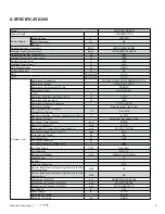
Страница 5: ...Electron expansion valve Cooling Operation Ambient Temperature Range 0F 0 4 118 4 Heating Operation AmbientTemperature Range 0F 4 75 2 Condenser Material Aluminum Fin copperTube Condenser Pipe Diameter inch Φ9 32 Rows Fin Gap mm inch 2 1 18 Coil length l X height H X coil width L inch 33 1 2X1 12X26 Fan Motor Speed rpm H M L rpm 630 Output of Fan Motor W 60 Fan Motor RLA A 0 62 Fan Motor Capacitor...

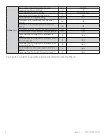
Страница 6: ...location Metric inch 1 4 Outer Diameter of Gas Pipe1 AC Pro Allocation Metric inch 3 8 Outer Diameter of Gas Pipe2 AC Pro Allocation Metric inch 3 8 Connection Pipe Max Height Distance indoor and indoor ft 32 8 Connection Pipe Max Height Distance indoor and out door and indoor up ft 32 8 Connection Pipe Max Height Distance indoor and out door and outdoor up ft 32 8 Max equivalent connection pipe l...

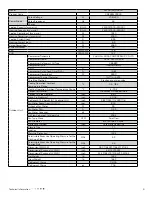
Страница 7: ... Cooling Operation Ambient Temperature Range 0F 0 4 118 4 Heating Operation AmbientTemperature Range 0F 4 75 2 Condenser Material Aluminum Fin copperTube Condenser Pipe Diameter inch Φ2 7 Rows Fin Gap mm inch 2 1 18 Coil length l X height H X coil width L inch 38 21 32X1 1 2X29 7 16 Fan Motor Speed rpm H M L rpm 800 Output of Fan Motor W 90 Fan Motor RLA A 0 59 Fan Motor Capacitor μF Air Flow Volu...

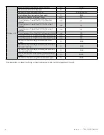
Страница 8: ...location Metric inch 1 4 Outer Diameter of Gas Pipe1 AC Pro Allocation Metric inch 3 8 Outer Diameter of Gas Pipe2 AC Pro Allocation Metric inch 3 8 Outer Diameter of Gas Pipe2 AC Pro Allocation Metric inch 3 8 Connection Pipe Max Height Distance indoor and indoor ft 32 8 Connection Pipe Max Height Distance indoor and out door and indoor up ft 32 8 Connection Pipe Max Height Distance indoor and ou...

Страница 9: ...hnical Information Service Manual utline Dimension Diagram 35 1 8 38 27 9 16 15 39 64 13 27 64 22 14 1 2 Unit inch Unit inch D 18 ND3EO GWHD 18 ND3FO GWHD 18 ND3GO WHD 24 ND3EO GWHD 24 ND3FO GWHD 24 ND3GO 38 37 64 35 1 8 13 27 64 17 21 64 31 7 64 22 14 1 2 AWHD 24 ND3GO ...

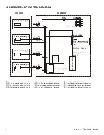
Страница 10: ...t electronic expansion valve B1 B unit electronic expansion valve C1 C unit electronic expansion valve D1 D unit electronic expansion valve A2 A unit gas pipe temperature sensor B2 B unit gas pipe temperature sensor C2 C unit gas pipe temperature sensor D2 D unit gas pipe temperature sensor A3 A unit liquid pipe temperature sensor B3 B unit liquid pipe temperature sensor C3 C unit liquid pipe temp...

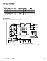
Страница 11: ...UTROOM TEMP SENSOR EXHAUST TEMP SENSOR 4YV COMP M1 FAN MOTOR EKV 5 5 BK FB YEGN G OFAN G G EH COMPRESSOR BAND HEATER RD RD HEAT C BN EKV WH 5 5 FA RD BK RT7 RT6 TEMP SENSOR TEMP SENSOR RD BK TEMP SENSOR LIQUID PIPE TEMP SENSOR GAS PIPE RT4 RT5 θ BK GY COM INNER BU BN BU BU BN BU YEGN G BU N1 AC L2 N2 E PE AP2 N1 AC L1 BN AP1 Main Board U V W RD BU YE BU RD YE L1 L1 G W X1 V U 4WAY T SENSOR POWER Y...

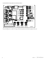
Страница 12: ...1 8 1 8 1 8 7 50 1 7 50 1 2 9 9 9 7521 3 16 21 9 9 1 225 81 7 1 1 225 81 7 1 1 1 3 0 1 2 5 1 3 1 7 1 7 7 4 4 4 57 57 1 225 81 7 1 5 725 2 2 2 7 50 1 2 7 50 1 9 9 3 16 21 7521 7521 3 16 21 9 9 78 78 57 57 57 57 78 20 11 5 1 57 57 9 8 9 29 203 8 203 3 36 33 57 7 6 1625 1 7 7 5 1 7 5 2035 6625 9 9 9 8 211 725 97 97 1 1 6 3 3 7 03 3 3 48 48 3 3 7 03 3 3 6 7 03 6 1625 6 1625 6 1625 6 1625 7 03 6 3 3 7 ...

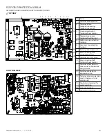
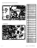
Страница 13: ...ion wire for indoor unit and outdoor unit 14 Neutral wire terminal for communication 15 Live wire terminal 16 Neutral wire terminal 5 2 PCB Printed Diagram TOP VIEW BOTTOM VIEW GWHD 18 ND3EO GWHD 18 ND3FO GWHD 18 ND3GO No Name 1 Terminal of compressor 2 Terminal of low temperature cooling temperature sensor 3 Overload protection terminal of compressor 4 Temperature sensor terminal of outdoor unit ...

Страница 14: ...c expansion vale for unit B 17 Electronic expansion vale for unit D 18 Communication wire with indoor unit 19 Neutral wire for counication 20 Live wire 21 Neutral wire 22 Reactor wire 1 23 Reactor wire 2 No Name 1 Terminal of compressor 2 Low pressure protection terminal 3 High pressure protection terminal 4 Overload protection terminal ofcompressor 5 Temperature sensor t erminal of outdoor unit 6...

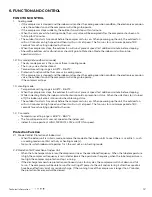
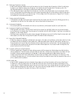
Страница 15: ...r fan will run at present speed for 1 additional minute before stopping While in Heating Mode the indoor unit will enter into cold air prevention status When the unit stops or is turned off the indoor unit enters into residual heat blowing status The outdoor fan starts 5 seconds before the compressor turns on When powering up the unit the outdoor fan will run 3 minutes on high speed and then it wi...

Страница 16: ...ing after the power has been cutoff and restored 2 7 Compressor Overload Protection When the compressor overload switch detects movement the indoor unit will display malfunction and it will stop the indoor unit from reaching the set temperature When the compressor stops for more than 3 minutes and the overload switch is reset the unit will resume normal operating status automatically If overload p...

Страница 17: ... become severed they MUST be repaired replaced by qualified technician 10 If the power cord or power connection wire is not long enough replace with specialized cable from manufacturer before proceeding with installation or repair DO NOT elongate these wires 11 An air switch MUST be installed if there is no plug found on the air conditioner The air switch MUST be all pole parting and the contact p...

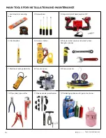
Страница 18: ...Screwdrivers 3 Impact drill drill head electric drill 4 Electroprobe 5 Universal meter 6 Torque wrench open end wrench inner hexagon spanner 7 Electronic leakage detector 8 Vacuum pump 9 Pressure meter 10 Pipe pliers pipe cutter 11 Pipe expander pipe bender 12 Soldering appliance refrigerant container ...

Страница 19: ...e Connect wires of indoor unit Bind up pipes and hang the indoor unit Install the support of outdoor unit select it according to the actual situation Fix outdoor unit Make the bound pipes pass through the wall hole and then connect outdoor unit Install drainage joint of outdoor unit only for cooling and heating unit Connect pipes of outdoor unit Connect wires of outdoor unit Neaten the pipes Vacuu...

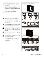
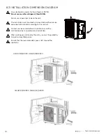
Страница 20: ... the outdoor unit one screw 2 Remove the cable clamp connect the power connection cable with the terminal at the row of connection and fix the connection The fitting line distributing must be consistent with the indoor unit terminal of line bank Wiring should meet that of indoor unit 3 Fix power connection wire by wire clamp 4 Ensure wire has been fixed well 5 Install the handle Wrong wire connect...

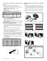
Страница 21: ... the indoor unit conversion joint Install the drain fitting and the drain hose for model with heat pump only Condensation is produced and flows from the outdoor unit when the appliance is operating in the heating mode In order not to disturb neighbours and to respect the environment install a drain fitting and a drain hose to channel the condensate water Install the drain fitting and rubber washer...

Страница 22: ... use any other refrigerant than R410A Do not use mineral oils to clean the unit The installation must be done by trained and qualified service personnel with reliability according to this manual Contact service center before installation to avoid the malfunction due to unprofessional installation When picking up and moving the units you must be guided by trained and qualified person Ensure that th...

Страница 23: ...voltage specified on the name plate The unit may bread down or the components may be burned out Are the lines and pipelines correctly in stalled The unit may bread down or the components may be burned out Has the unit been safely grounded Risk of electrical leakage Are the models of lines in conformity with requirements The unit may bread down or the components may be burned out Are there any obst...

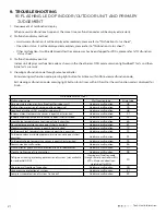
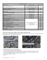
Страница 24: ...lfunction protection of jumper cap for indoor unit Hardware malfunction C5 Feedback of without IDU motor for indoor unit Hardware malfunction H6 Indoor ambient temperature sensor is open short circuited Hardware malfunction F1 Indoor evaporator temperature sensor is open short circuited Hardware malfunction F2 Liquid valve temperature sensor is open short circuited Hardware malfunction b5 Gas valv...

Страница 25: ...dn 3 L n o i t c n u f l a m e r a w d r a H 1 n a f r o o d t u o f o n o i t c e t o r p n o i t c n u f l a M Detection status of wrong connection of communication wire or malfunction of electronic expansion valve Operation status dd 7 E s u t a t s n o i t a r e p O t c i l f n o c e d o M o F s u t a t s n o i t a r e p O e d o m g n i l c y c e r t n a r e g i r f e R L A s u t a t s n o i t...

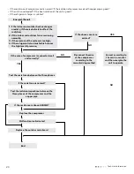
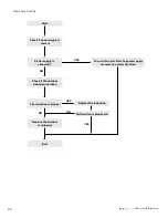
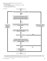
Страница 26: ...if there is obstacle to affect the radiation 2 if the indoor and outdoor fans are running normally 3 if the pressure of the system is too high 4 if the refrigerant is too much which causes the high level of pressure If the wire of compressor is connected well and correctly NO Test the resistance between the three phases YES If the resistance is normal Replace the compressor End NO NO If the resist...

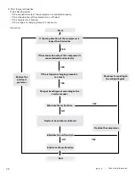
Страница 27: ...cking points If the wiring of the induction is connected well and if the induction is broken If the mainboard is broken Flow chart For 18k Power supply is abnormal Start Check if power supply is normal End Replace the outdoor mainboard Turn on the unit after power supply resumes normal YES NO ...

Страница 28: ...tart Check if power supply is normal End Replace the outdoor mainboard Turn on the unit after the power supply resumes to normal situation YES NO Check if the outdoor induction is broken The induction is broken Replace the induction Malfunction is eliminated YES NO NO YES ...

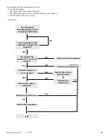
Страница 29: ...ate the malfunction The eletric expansion valve is broken Replace the outdoor mainboard NO NO 3 Compressor desynchronizing malfunction Main checking points If the pressure of the system is too high If the eletric expansion valve is working normally or it is broken If the radiation of the unit is good Flow chart Replace the compressor Eliminate the malfunction NO Replace the electric expansion valv...

Страница 30: ... too much NO Eliminate the malfunction YES YES Replace the compressor Check if fan terminal is connected well Improve radiation situation of the unit such as cleaning the heat exchanger improve ventilation Turn on the unit after the power supply voltage resumes normal Charge refrigerant according to the service manual Replace the outdoor unit Replace the fan capacitor NO NO YES YES NO NO YES ...

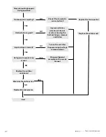
Страница 31: ...s connected well Check the coil of the eletric expansion valve replace it if it is broken Check the refrigerant status if there is refrigerant leakage recharge it according to the service manual YES YES Eliminate the malfunction NO NO YES Replace outdoor mainboard Reconnect according to the wiring diagram YES YES Replace the overload protector Note the detection method of the coil of the eletric e...

Страница 32: ...If the connection wire of the compressor is connected well and correctly Start If the stop duration of the compressor is longer than 3 minutes End Eliminate the malfunction If the refrigerant charging amount is too much Charge the refrigerant according to the service manual Replace the outdoor mainboard YES YES Eliminate the malfunction NO NO YES Eliminate the malfunction Reconnect according to th...

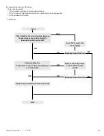
Страница 33: ...oken Flow chart Check whether the temperature senspr is normal according to resistance table Start Check whether the wiring terminal between temperature sensor and controller is loosened or poorly contacted End Eliminate the malfunction Replace the controller with the same model Insert the temperature sensor tightly Replace the temperature sensor with the same model YES YES Eliminate the malfuncti...

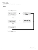
Страница 34: ... wire of DC fan is connected reliably If it is loose Flow chart If the connection wire of DC fan is loose Start Check if the outdoor fan is blocked by foreign objects End Replace the outdoor mainboard Turn on the unit after removing the foreign objects Turn on the unit after the connection wire is properly connected NO YES NO YES ...

Страница 35: ...nction of some indoor units De energize check if the connection wire of indoor and outdoor unit and the wire of the electric box is connected correctly End The malfunction indoor unit resumes normal De energize change the communication wire of the well communicated indoor unit and malfunction indoor unit then energize the unit and wait for 3 min Replace the mainboard of the malfunction indoor unit...

Страница 36: ...outdoor unit and the wire of the eletric box is connected correctly End Check if there is power input between the netrual wire and live wire of the outdoor mainboard De energize check if the connection wire between the outdoor mainboard and the filter board according to the wiring diagram The connection wire is broken NO Is there power input YES YES Replace the outdoor mainboard Reconnect accordin...

Страница 37: ...door fan is working normally Replace the outdoor mainboard 9 Anti high temperatureand overload malfunction Main checking points If the outdoor ambient temperature is within the normal range If the indoor fan and outdoor fan are running normally If the indoor and outdoor radiation environment is good Flow chart Improve the radiation environment of the unit YES Check if the terminal of the fan is co...

Страница 38: ...n for indoor unit and outdoor unit is improper Check whether the installation postion is proper according to installation requirement for air conditioner Adjust the installation position and install the rainproof and sunproof for outdoor unit Refrigerant is leaking Discharged air temperature during cooling is higher than normal discharged wind temperature Discharged air temperature during heating ...

Страница 39: ...pressor Cylinder of compressor is blocked Compressor cant operate Repair or replace compressor 6 Air Conditioner is Leaking Possible Causes Discriminating Method Air conditioner Status Troubleshooting Drain pipe is blocked Water leaking from indoor unit Eliminate the foreign objects inside the drain pipe Drain pipe is broken Water leaking from drain pipe Replace drain pipe Wrapping is not tight Wa...

Страница 40: ...RTS LIST AWHD 18 ND3EO AWHD 18 ND3FO AWHD 18 ND3GO 42 Installation and Maintenance Service Manual 10 Exploded View and Parts List GWHD 18 ND3EO GWHD 18 ND3FO GWHD 18 ND3GO The component picture is only for reference please refer to the actual product ...

Страница 41: ...ut off Valve 071302391 071302391 1 17 Cut off Valve 07130239 071302391 1 18 Valve Cover 19 Electric Expand Valve Fitting 43000084 43000084 1 20 Electric Expand Valve Fitting 4300008401 4300008401 1 21 Temperature Sensor 39000073 39000073 1 22 Temperature Sensor 3900007301 3900007301 1 23 Wiring Clamp 26115004 26115004 1 24 Temperature Sensor 39000073 39000073 1 25 Rear Grill 01574100003 01473043 1...

Страница 42: ...rt Sub Assy 0171312802P 1 16 Cut off Valve 07130239 1 17 Cut off Valve 071302391 1 18 Valve Cover 19 Electric Expand Valve Fitting 43000084 1 20 Electric Expand Valve Fitting 4300008401 1 21 Temperature Sensor 39000073 1 22 Temperature Sensor 3900007301 1 23 Wiring Clamp 26115004 1 24 Temperature Sensor 39000073 1 25 Rear Grill 01473043 1 26 Condenser Assy 011002000279 1 27 Clapboard Assy 01233153...

Страница 43: ...ormation AWHD 24 ND3EO AWHD 24 ND3FO AWHD 24 ND3GO 45 Installation and Maintenance Service Manual GWHD 24 ND3EO GWHD 24 ND3FO GWHD 24 ND3GO The component picture is only for reference please refer to the actual product ...

Страница 44: ...y 02204100008 02204100008 1 21 Electric Expand Valve Fitting 4300008402 4300008402 1 22 Electric Expand Valve Fitting 4300008401 4300008401 1 23 Electric Expand Valve Fitting 43000084 43000084 1 24 Temperature Sensor 3900030901 3900030901 1 25 Temperature Sensor 3900007306 3900007306 1 26 Temperature Sensor 3900007305 3900007305 1 27 Wiring Clamp 26115004 26115004 1 28 Temperature Sensor 39000073 ...

Страница 45: ...02204100008 02204100008 1 21 Electric Expand Valve Fitting 4300008402 43000084 1 22 Electric Expand Valve Fitting 4300008401 4300008401 1 23 Electric Expand Valve Fitting 43000084 4300008402 1 24 Temperature Sensor 3900030901 3900030901 1 25 Temperature Sensor 39000073 39000073 1 26 Temperature Sensor 3900007305 3900007306 3900007305 3900007306 1 27 Wiring Clamp 26115004 26115004 1 28 Temperature ...

Страница 46: ...on cover AWHD 18 ND3EO AWHD 18 ND3FO AWHD 18 ND3GO 11 REMOVAL PROCEDURE 48 Installation and Maintenance Service Manual 11 Removal Procedure Warning Be sure to wait for a minimum of 20 minutes after turning off all power supplies and discharge the refrigerant completely before removal Steps Procedure Remove the screws fixing big handle and right side plate to remove the big handle 1 Remove big hand...

Страница 47: ...t to remove the panel 2 Remove top cover 3 Remove grille 4 Remove panel top cover grille panel 49 lation and Maintenance Steps Procedure Remove the screws fixing top cover panel and left right side plate to remove top cover Remove the screws fixing grille and panel to remove the grille on the panel Remove the screws fixing panel chassis and motor support to remove the panel 2 Remove top cover 3 Re...

Страница 48: ...ard grille 7 Remove left side plate right side plate guard grille left side plate 50 Installation and Maintenance Steps Procedure Remove the screws fixing right side plate valve support and guard grille to remove the right side plate Remove the screws fixing guard grille and left side plate to remove guard grille Remove the screws fixing chassis and condenser support to remove the left side plate ...

Страница 49: ...e the tapping screws fixing motor pull out the pin of leading wire for motor and remove the screws fixing motor support and chassis to remove the motor and motor support sub assy 9 Remove axial fan blade 10 Remove motor and motor support sub assy 8 Remove condenser support condenser support axial fan blade motor motor support sub assy 51 on and Maintenance ce Manual Steps Procedure Remove the scre...

Страница 50: ... sub assy PFC electrical inductance four way valve sub assy 52 Installation and Maintenance Service Manual Steps Procedure Remove the tapping screws fixing isolation sheet loosen the wire binds pull out the terminal lift to remove the electric box sub assy Remove the screws fixing PFC electrical inductance and isolation sheet to remove the PFC electrical inductance Welding cut the welding point jo...

Страница 51: ...ion pipe sub assy suction pipe sub assy liquid receiver isolation sheet assy 53 tion and Maintenance Steps Procedure Welding cut the welding point jointing the suction pipe sub assy compressor and liquid receiver to remove the suction pipe sub assy Remove the screws fixing isolation sheet and liquid receiver and lift to remove the liquid receiver Remove the screws fixing isolation sheet and conden...

Страница 52: ... assy 19 Remove EXV assy 17 Remove compressor compressor valve support assy EXV assy 54 Installation and Maintenance Steps Procedure Remove the screw nuts fixing compressor foots and chassis with spanner as well as the foot cushion to remove the compressor Remove the screws fixing valve support assy and chassis sub assy to remove the valve support assy Welding cut the welding point jointing EXV su...

Страница 53: ...onnecting the top panel with the front panel and the right side plate and then remove the top panel 2 Remove grille front side plate and panel Remove Remove the 1 screw connecting the front side plate and the panel and then remove the front side plate the 2 screws connecting the grille and the panel and then remove the grille b Steps Procedure grille front side plate top panel 55 tallation and Mai...

Страница 54: ...e right side plate and left side plate Remove the screws connecting the right side plate with the chassis the valve support and the electric box and then remove the right side plate assy panel right side plate Remove the screws connecting the left side plate and the chassis and then left side plate remove the left side plate assy 56 Installation and Maintenance c a b Remove the 5 screws connecting...

Страница 55: ...ll the electric box upwards to remove it Remove the 4 tapping screws fixing the motor disconnect the leading wire insert of the motor and then remove the motor Remove the 2 tapping screws fixing the motor support and then pull the motor support upwards to remove it electric box fan motor axial flow blade Remove the nuts fixing the blade and then remove the axial flow blade a b 57 stallation and Ma...

Страница 56: ...tion sheet Remove the 3 screws fixing the isolation sheet and then remove the Isolation sheet Isolation sheet Discharge the refrigerant completely unsolder the pipelines connecting the compressor and the condenser assy and then remove the 4 way valve assy 4 way valve assy 4 way valve assy Connection Pipe soundproof sponge 58 Installation and Maintenance Service Manual a b 6 Remove soundproof spong...

Страница 57: ...he screws connecting the support and condenser assy and thenremove the support 59 stallation and Maintenance Service Manual 8 Remove Remove the 3 foot nuts fixing the compressor and then remove the compressor Remove the screws connecting the support and condenser assy and thenremove the support 9 Remove compressor Cut off Valve Cut off Valve and Valve Support Valve Support 10 Remove support suppor...

Страница 58: ...11 Remove condenser sub assy Remove the chassis sub assy and condenser sub assy 60 Installation and Maintenance Service Manual 11 Remove condenser sub assy Remove the chassis sub assy and condenser sub assy chassis sub assy condenser sub assy ...

Страница 59: ...ndard length of connection pipe 16 40ft 24 61ft 26 2ft 2 Min length of connection pipe is 9 84ft 3 Max length of connection pipe and max high difference See the specification 4 The additional refrigerant oil and refrigerant charging required after prolonging connection pipe After the length of connection pipe is prolonged for 32 81ft at the basis of standard length you should add 0 0013gal of refr...

Страница 60: ...haper and prevent the burrs from getting into the pipe C Put on suitable insulating pipe D Put on union nut Remove union nut on the indoor connection pipe and outdoor valve install the union nut on the pipe E Expand the port Note A is different according to the diameter please refer to the sheet below Outer diameter inch A inch Max Min Ф0 24 0 25 1 4 0 05 0 03 Ф0 37 3 8 0 06 0 04 Ф0 47 0 50 1 2 0 ...

Страница 61: ...6 0 717 24 8 60 23 95 9 779 165 2 2 28 235 4 0 697 26 6 57 18 96 8 9 382 167 2 206 237 2 0 678 28 4 54 31 98 6 9 003 168 8 2 133 239 0 66 30 2 51 59 100 4 8 642 170 6 2 064 240 8 0 642 32 49 02 102 2 8 297 172 4 1 997 242 6 0 625 33 8 46 6 104 7 967 174 2 1 933 244 4 0 608 35 6 44 31 105 8 7 653 176 1 871 246 2 0 592 37 4 42 14 107 6 7 352 177 8 1 811 248 0 577 39 2 40 09 109 4 7 065 179 6 1 754 2...

Страница 62: ...5 2 3 04 235 4 0 93 26 6 76 24 96 8 12 51 167 2 94 237 2 0 904 28 4 72 41 98 6 12 168 8 2 844 239 0 88 30 2 68 79 100 4 11 52 170 6 2 752 240 8 0 856 32 65 37 102 2 11 06 172 4 2 663 242 6 0 833 33 8 62 13 104 10 62 174 2 2 577 244 4 0 811 35 6 59 08 105 8 10 2 176 2 495 246 2 0 77 37 4 56 19 107 6 9 803 177 8 2 415 248 0 769 39 2 53 46 109 4 9 42 179 6 2 339 249 8 0 746 41 50 87 111 2 9 054 181 4...

Страница 63: ...19 147 2 10 54 217 4 3 04 8 6 323 9 78 8 47 08 149 10 18 219 2 2 955 10 4 306 2 80 6 45 07 150 8 9 827 221 2 872 12 2 289 6 82 4 43 16 152 6 9 489 222 8 2 792 14 274 84 2 41 34 154 4 9 165 224 6 2 715 15 8 259 3 86 39 61 156 2 8 854 226 4 2 64 17 6 245 6 87 8 37 96 158 8 555 228 2 2 568 19 4 232 6 89 6 36 38 159 8 8 268 230 2 498 21 2 220 5 91 4 34 88 161 6 7 991 231 8 2 431 23 209 93 2 33 45 163 ...

Страница 64: ...61 Technical Information ...

Отзывы: