background image


Figure 301


Sheet 01 - Gravity Fueling - Fueling Provisions


ABX Air Inc. 
Printed: 8/27/2010 at 12:10:53 
PM 
REV 11 2008/12/11

DC-9 

MAINTENANCE MANUAL


EFFECTIVITY: 900-905, 909, 928, 930, 934, 939, 
953-960, 962-964, 980-984, 986 

12-12-00-3

CONFIG 00

Page 7

1999/11/15

This page must not be retained for reference

Содержание DC-9

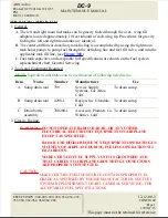
Страница 1: ...upply Systems Los Altos Calif To drain sump B Sump drain tool 4298 1 Roylyn Inc Glendale Calif To drain sump C Drain bottle assembly 700200 1 Accessory Products Co Whittier Calif To drain sump 3 Gravity Fueling WARNING DO NOT OPERATE RADIO RADAR OR ANY OTHER ELECTRICAL ELECTRONIC EQUIPMENT ON AIRPLANE EXCEPT AS SPECIFIED RADAR AND HIGH FREQUENCY EQUIPMENT OPERATING IN VICINITY OF AIRPLANE DURING F...

Страница 2: ...TE If external electrical power is not available to supply the airplane load buses airplane battery power will automatically be supplied to the ground refueling circuit when the fueling control panel power switch is placed in the on position Conservative use of airplane battery power for fuel quantity indication is permissible c Momentarily hold fuel quantity repeater indicator gage test switch in...

Страница 3: ...ediately after upward force is applied to tool The sump tool permits a fluid flow rate in excess of 3 gallons per minute creating the siphoning action necessary to remove a maximum amount of free water from the tank sumps and thus reduces corrosion and soaping time b Drain tank sump until water ceases to flow NOTE Fuel tank sumps should be drained after sufficient time approximately 45 minutes for...

Страница 4: ...t position to test indicators pointers will move towards zero when switch is released pointers will return to original quantity 6 Determine fuel load 7 Place center and forward auxiliary tank fuel fill valve control switch in auto fill position verify that tank fill valve manual control lever s moves to open position see Figure 302 8 If applicable tank fuel fill valve s do not open use following p...

Страница 5: ...lbs for forward auxiliary tank 17 If center and forward auxiliary tank fuel fill valve s required manual control to open place boost pump switches in off position when either partial or full tank s fuel loading is attained 18 Place fueling control panel center and forward auxiliary tank fuel fill valve s control switch in closed position 19 If main tank maximum fuel load is desired fuel each main ...

Страница 6: ...drain valves operate identically a Insert probe of drain tool in center recess of sump drain valve and apply upward force NOTE Fuel should flow immediately after upward force is applied to tool The sump tool permits a fluid flow rate in excess of 3 gallons per minute creating the siphoning action necessary to remove a maximum amount of free water from the tank sumps and thus reduces corrosion and ...

Страница 7: ...ovisions ABX Air Inc Printed 8 27 2010 at 12 10 53 PM REV 11 2008 12 11 DC 9 MAINTENANCE MANUAL EFFECTIVITY 900 905 909 928 930 934 939 953 960 962 964 980 984 986 12 12 00 3 CONFIG 00 Page 7 1999 11 15 This page must not be retained for reference ...
Страница 8: ...rol Station ABX Air Inc Printed 8 27 2010 at 12 10 53 PM REV 11 2008 12 11 DC 9 MAINTENANCE MANUAL EFFECTIVITY 900 905 909 928 930 934 939 953 960 962 964 980 984 986 12 12 00 3 CONFIG 00 Page 8 1999 11 15 This page must not be retained for reference ...

Страница 9: ...ueling Transfer Schematic ABX Air Inc Printed 8 27 2010 at 12 10 53 PM REV 11 2008 12 11 DC 9 MAINTENANCE MANUAL EFFECTIVITY 900 905 909 928 930 934 939 953 960 962 964 980 984 986 12 12 00 3 CONFIG 00 Page 9 1999 11 15 This page must not be retained for reference ...

Отзывы: