2-4
Chapter2
CX6
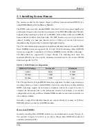
2-3. Installing System Memory
The memory module for the Camino chipset is different from conventional DIMM. It is
called RIMM (
R
ambus
I
n-line
M
emory
M
odule).
The RIMM conforms to the standard DIMM form factor, but it is not pin-compatible. Its
architecture is based on the electrical requirements of the DRC (
D
irect
R
ambus
C
hannel)
high-speed bus operating at a clock rate of 400MHz which enables a data rate of 800MHz
because data is clocked on both clock edges. The DRC bus also uses a two byte-wide data
channel, resulting in a peak data transfer rate of 1.6Gbytes per second. The bus uses
transmission line characteristics to maintain high signal integrity.
The CX6 with Camino chipset supports a single Direct Rambus Channel. 300 and 400 MHz
Direct RDRAM devices are supported. 64, 128 and 256 Mbit technology Direct RDRAM
devices are supported. A maximum of 32 Direct RDRAM devices (64Mbit technology =
256 Mbyte Max) are supported for a single channel. The following table shows the
maximum DRAM array size and the minimum increment size for the various DRAM
densities supported for CX6.
Table 2-1 Valid Memory Configurations
RDRAM Technology
Increments
Maximum
64Mbit
8MB
256MB
128Mbit
16MB
512MB
256Mbit
32MB
1GB
The CX6 provides two 184-pin RIMMs for memory expansion. You have to pay attention to
two things before you want to install RIMMs. Firstly, the serial nature of Direct Rambus
RIMM technology requires that all memory expansion sockets be occupied in order to
complete the transmission line to the termination resistors. For example, a two sockets
configuration where only one Direct Rambus RIMM module is used would require the use
of a continuity module.
Secondly, a single Direct Rambus Channel can connect directly to as many as 32 Direct
RDRAMs placed on a total of two RIMM modules.
How to install RIMMs
Generally, installing Direct RDRAM modules to your motherboard is an easy thing to do.
You can refer to figure 2-3 and 2-4 to see what a 184-pin Direct RDRAM module and
continuity module look like.
Содержание CX6
Страница 2: ......
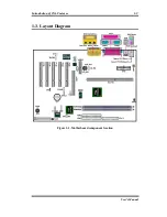
Страница 13: ...Introduction of CX6 Features 1 9 User s Manual 1 3 Layout Diagram Figure 1 1 Motherboard component location ...
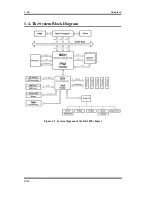
Страница 14: ...1 10 Chapter1 CX6 1 4 The System Block Diagram Figure 1 2 System diagram of the Intel 820 chipset ...
Страница 78: ...3 44 Chapter3 CX6 ...
Страница 84: ...B 4 Appendix B CX6 ...
Страница 90: ...D 4 Appendix D CX6 ...
Страница 96: ...E 6 Appendix E CX6 ...
Страница 104: ...G 4 Appendix G CX6 ...
Страница 110: ...H 6 Appendix H CX6 ...

